A waveguide circulator in microwaves uses ferrite materials and Faraday rotation to direct RF signals unidirectionally (e.g., 8-12GHz X-band) with <0.5dB insertion loss and >20dB isolation, handling 50W+ CW power to protect transmitters in radar/transceiver systems by preventing reflected signal damage.
Table of Contents
What It Is and Main Jobs
A typical commercial C-band (4-8 GHz) radar circulator might handle an average continuous wave (CW) power of 500 watts and provide isolation greater than 20 dB between the transmitter and receiver ports. This isolation is paramount; it prevents the high-power transmitted signal, which can be peaks of 50 kW or more, from damaging the sensitive low-noise amplifier (LNA) in the receiver chain, which might have a damage threshold of only 1 watt.
In a standard radar setup operating at 2.8 GHz (S-band), a circulator ensures that over 99% of the transmitted energy is directed toward the antenna, while less than 1% leaks back toward the receiver. This translates to an insertion loss from the transmitter to the antenna of just 0.2 dB—meaning 95% of the power reaches its intended destination—and an isolation of 20 dB, which reduces the reflected power seen by the receiver by a factor of 100. This isn’t just about efficiency; it’s a hard requirement for system survivability. The financial implication of not using one is severe: a single damaged LNA can cost between 20,000 to replace, not including the downtime for a critical system like an air traffic control radar, which can incur costs of thousands of dollars per hour. The circulator itself, a relatively simple component priced between 2,000, acts as a first-line defense, making it one of the most cost-effective insurance policies in a high-power RF system.
The fundamental principle behind its operation is the non-reciprocal phase shift experienced by microwave signals as they pass through the magnetized ferrite post. This phase shift, which can be precisely tuned to be 180 degrees for the desired frequency, is what creates the unique one-way signal path, making reverse transmission highly inefficient.
By isolating the receiver from the noisy transmit path, it ensures the receiver’s low noise figure (often below 2 dB) is not degraded. This directly increases the radar’s effective range, as a 1 dB improvement in noise figure can translate to a 10-15% increase in detection range. The physical size of these components is directly tied to the wavelength they are designed for. A unit for the 24 GHz ISM band might be just 4 cm x 4 cm x 2 cm, while one for a 400 MHz military comms band could be over 30 cm long. Their operational lifetime is typically defined by the permanent magnet’s stability, often rated for 20+ years with a magnetic flux loss of less than 0.1% per year, ensuring consistent performance over the long term with minimal maintenance.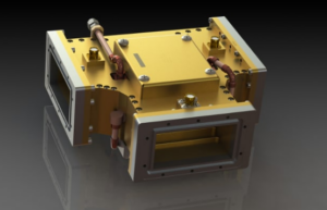
How It Guides Waves One Way
For a standard X-band (8-12 GHz) circulator, a cylindrical ferrite post, typically 3 mm in diameter and 5 mm tall, is precisely centered inside a WR-90 rectangular waveguide measuring 22.86 mm by 10.16 mm. This entire assembly is subjected to a strong, static magnetic bias field, usually provided by a ring of permanent magnets generating a field strength between 1500 to 3000 Oersteds (Oe). This field permanently magnetizes the ferrite, saturating it to create a stable internal electron precession. When a 10 GHz signal enters at Port 1, its rotating magnetic field interacts with these precessing electrons. The interaction causes the signal’s phase to advance if it rotates with the precession and delay if it rotates against it. This creates a precise phase difference of approximately 120 degrees between the two rotational components of the wave.
The physical geometry of the junction—most commonly a Y-junction or triangle—is designed so that this phase-shifted wave constructively interferes only at one specific port and destructively interferes at all others. For a signal entering Port 1, the phase conditions are perfect for it to emerge with less than 0.3 dB of loss (a 93% power transfer) at Port 2. Meanwhile, the path back from Port 2 to Port 1 is designed to be out of phase by over 180 degrees, resulting in high isolation, typically 23 dB or more. This means less than 0.5% of the power sent into Port 2 can leak back into Port 1. The performance is highly dependent on the magnetic bias field strength. If the field drops by just 5% due to aging or temperature changes (e.g., from 25°C to 85°C), the isolation can degrade by 3 to 5 dB, significantly increasing the risk of receiver damage. The ferrite material itself, often yttrium iron garnet (YIG), has a Curie temperature around 280°C, beyond which it loses its magnetic properties entirely.
| Frequency Band | Typical Waveguide Standard (WR) | Internal Dimensions (mm) | Typical Ferrite Diameter | Isolation (min) | Insertion Loss (max) | Bandwidth (GHz) |
|---|---|---|---|---|---|---|
| Ku-band (12-18 GHz) | WR-62 | 15.80 x 7.90 | 2.1 mm | 20 dB | 0.4 dB | 2.5 GHz |
| C-band (4-8 GHz) | WR-112 | 28.50 x 12.60 | 5.0 mm | 23 dB | 0.25 dB | 1.0 GHz |
| Ka-band (26-40 GHz) | WR-28 | 7.11 x 3.56 | 1.2 mm | 18 dB | 0.6 dB | 5.0 GHz |
This precise interplay of magnetic physics and microwave engineering allows a circulator to reliably handle peak power levels exceeding 100 kW in pulsed radar systems. The response time of this non-reciprocal effect is virtually instantaneous, on the order of picoseconds, as it depends on electron spin precession rather than slower mechanical or electronic switching. The operational lifetime, often rated for over 100,000 hours (more than 10 years), is primarily determined by the stability of the permanent magnet’s field strength, which can decay at a rate of less than 0.1% per year.
Key Specs for Picking One
A poor match can degrade an entire system’s efficiency or cause permanent damage. For a C-band radar application operating at 5.4 GHz, you might be comparing units where a 0.5 dB difference in insertion loss translates to over 10% of your transmitted power being wasted as heat. The isolation spec is your primary defense mechanism; a value of 20 dB means only 1% of power leaks into an isolated port, but increasing that to 25 dB (reducing leakage to 0.3%) could double the component’s cost from 2,500. The operating bandwidth is equally critical: a circulator with a 200 MHz bandwidth centered at your frequency is useless if your system requires 500 MHz of instantaneous bandwidth. Environmental factors like a wide operating temperature range from -40°C to +85°C can add a 15-20% premium to the base price but are non-negotiable for outdoor or military deployments.
The absolute first parameter is center frequency and bandwidth. Your choice is dictated by your system’s operating band. A Ka-band satellite transceiver at 30 GHz will require a vastly different circulator than an S-band radar at 3 GHz. You must match the circulator’s specified center frequency exactly and ensure its operational bandwidth, often defined by the -20 dB isolation points, covers your entire signal band. A unit rated for 10-12 GHz will perform poorly if your signal is at 12.5 GHz. Next, scrutinize insertion loss, which is the signal power lost going from the input to the output port. A spec of 0.3 dB means 93% of your power gets through, while a lossy 0.6 dB unit wastes 12% of your power as heat, which becomes a major thermal issue at 500 W of input power. Isolation defines how well the device blocks reverse signals. 20 dB of isolation is a common minimum, blocking 99% of reverse power, but for sensitive systems, 25 dB (99.7% blocking) or even 30 dB (99.9% blocking) is standard to protect expensive amplifiers.
| Specification | Typical Standard Performance | High Performance | Real-World Impact of a 10% Deviation |
|---|---|---|---|
| Insertion Loss | 0.4 dB | 0.2 dB | +0.04 dB loss: Wastes an additional ~1% of transmit power as heat. |
| Isolation | 20 dB | 25 dB | -2 dB (18 dB): Reverse power leakage increases by over 60%, risking receiver damage. |
| VSWR | 1.25 | 1.15 | Increase from 1.25 to 1.38: Reflected power jumps from 1.1% to 1.7%, affecting transmitter stability. |
| Power Handling (Avg.) | 500 W | 1000 W | Operating a 500 W unit at 550 W: Internal temperature may rise by 15-20°C, shortening lifespan. |
| Operating Temp. | 0°C to +70°C | -40°C to +85°C | Using a commercial-grade unit (0°C to +70°C) in a -10°C environment: Isolation may drop by 3-5 dB. |
A VSWR of 1.20 at the input port indicates that less than 1% of the signal power is reflected back towards your source, ensuring stable transmitter operation. A higher VSWR of 1.35 reflects over 2% of your power, which can cause amplifier instability and frequency pulling. Power handling has two values: average and peak. A circulator rated for 1 kW average and 10 kW peak power must dissipate the heat generated from the 0.4 dB of loss (about 100 watts) without its internal temperature exceeding its maximum rating of 130°C. Exceeding the average power rating by 20% can raise internal temperatures by 30°C or more, potentially demagnetizing the internal ferrite and permanently destroying the device. Finally, mechanical specs are vital. The flange type (e.g., CPR-137, UG-419) must match your waveguide system, and the weight, which can range from 500 grams for a C-band unit to over 3 kg for a high-power L-band circulator, must be supported by your structure. The operating temperature range is not a suggestion; performance parameters are only guaranteed between the stated minimum and maximum temperatures, usually -30°C to +70°C for commercial units and -55°C to +100°C for military-spec versions.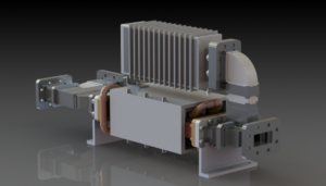
Where It’s Used: Real Examples
In radar systems, the circulator is a critical power management and protection device. A naval radar system might employ a high-power L-band (1-2 GHz) circulator capable of handling 1.5 MW of peak power and 5 kW of average power. The insertion loss must be exceptionally low, typically <0.2 dB, to ensure that over 95% of the generated power is radiated outwards towards the antenna, rather than being converted into waste heat that must be dissipated. The isolation performance of 23 dB ensures that the fraction of a percent of power that is reflected from the antenna (due to a VSWR of 1.3) is directed towards a matched load, not back into the transmitter, preventing potential damage and instability. In satellite transponders, the circulator’s role is to enable full-duplex communication. A typical C-band communications satellite uses a circulator with a 500 MHz operational bandwidth to route signals between the common antenna, the 40 watt Traveling Wave Tube Amplifier (TWTA), and the receiver front-end. The circulator’s performance directly impacts the link budget; a 0.1 dB reduction in insertion loss can translate to a measurable increase in data throughput for thousands of users on the ground.
In medical MRI systems, circulators are used at lower microwave frequencies (e.g., 300-400 MHz) to protect the sensitive receiver coils from the high-power RF pulses (e.g., 5 kW for 1-2 ms) used to excite nuclei, ensuring the clarity of the received signal used to construct images.
The telecommunications industry relies on circulators for signal separation in base stations. A 5G massive MIMO antenna operating at 3.5 GHz might use 32 or 64 individual transceiver chains, each requiring a circulator to isolate the transmitter output from the receiver input. These components are selected for their compact size (often < 3 cm³), wide bandwidth (>200 MHz), and ability to operate reliably for over 10 years with minimal maintenance.
In scientific and research applications, precision is paramount. A particle accelerator like a cyclotron might use a circulator at 100 MHz to handle continuous wave (CW) powers of 50 kW to feed RF energy into the acceleration cavities. The required isolation must exceed 30 dB to prevent noise and reflected power from disrupting the extremely stable RF source, which must maintain a frequency stability of less than ±1 part per million (ppm). The cost of failure here is not just financial but also operational, leading to days or weeks of lost experimental time for a multi-million-dollar facility.
Mounting and Cooling Needs
Installing a waveguide circulator is a precise mechanical operation, not just a simple bolt-on task. Improper mounting can warp the flange, misalign the internal components, and degrade electrical performance by >3 dB. For a high-power L-band circulator handling 50 kW peak power, a mounting torque deviation of just 2 in-lbs from the specified 15 in-lbs can compromise the waveguide seal, leading to multipaction breakdown or increased VSWR. The thermal management calculus is equally critical; a circulator with 0.3 dB of insertion loss processing 2 kW of average input power must dissipate ~140 watts of continuous heat (calculated as ). Without effective cooling, the internal ferrite’s temperature can skyrocket from a 25°C ambient to over 120°C in under 5 minutes, risking permanent demagnetization and a total loss of non-reciprocal function, effectively bricking a $8,000 component.
For a unit handling 1 kW average power, the baseplate must be mounted to a cold wall or heat sink with a surface flatness better than 0.05 mm and a surface roughness under 1.6 μm RMS. You must use a thermally conductive interface material like a 0.1 mm thick boron nitride sheet or a thermal grease with a conductivity of >3 W/m·K. The required interface pressure should be a minimum of 50 psi (345 kPa) across the entire contact area. Without this, the thermal impedance from the ferrite to the ambient might be 0.5°C/W, but with a proper interface and mounting, this can be reduced to 0.2°C/W. This means for 140 watts of dissipated power, the internal temperature rise would be 28°C instead of 70°C, keeping the ferrite well within its 85°C maximum operating temperature for a 100,000-hour lifespan.
For extreme power levels above 3 kW average, forced air cooling is mandatory. This requires an airflow of at least 200 linear feet per minute (LFPM) across the fins. The air temperature must be monitored; if the inlet air exceeds 40°C, the internal temperature may still exceed safe limits. In these cases, a secondary closed-loop liquid cooling system is integrated, pumping a 50/50 water-glycol mixture at a flow rate of 1-2 liters per minute through channels in the mounting baseplate to maintain the interface temperature at 30°C ±5°C. The thermal cycle is relentless; every on/off cycle causes expansion and contraction. The aluminum housing expands at a rate of 23 μm/m°C, while the stainless steel bolts expand at 16 μm/m°C. Over 10,000 operational cycles, this differential thermal expansion can loosen mounts if not properly torqued and secured with locking washers, leading to a 20% increase in thermal impedance over a 5-year period. Regular maintenance every 12-18 months should include re-checking torque specs and replacing dried-out thermal interface materials to prevent performance drift and avoid a 15% reduction in the unit’s power handling capability.


