The High Power Differential Phase Shift WG Circulator operates in X-band (8-12 GHz), supporting 500W peak input power with <0.5 dB insertion loss and >40 dB isolation. Its optimized ferrite structure minimizes phase error to ±2°, ensuring stable signal routing in high-power radar systems.
Table of Contents
What It Is and How It Works
A High Power Differential Phase Shift Waveguide Circulator is a specialized passive microwave device used to control the direction of signal flow in high-frequency communication and radar systems. Operating typically within the 18–40 GHz frequency range, it handles average power levels of 200W and peak power up to 500W. Unlike traditional coaxial circulators, this type uses a rectangular waveguide interface, which reduces insertion loss to less than 0.3 dB and improves heat dissipation. Its core function is to route electromagnetic signals sequentially between three or four ports in a circular manner, offering isolation exceeding 20 dB between adjacent ports. This makes it especially useful in high-power applications like satellite transmitters and military radar, where signal integrity and power handling are critical.
Inside, a ferrite material is biased by a permanent magnet, creating a magnetic field with a strength of roughly 1500–2500 Gauss. When a microwave signal enters, say, Port 1, its phase is altered asymmetrically due to the Faraday rotation effect. This forces the signal to exit only through Port 2, not back to Port 1 or to Port 3. The differential phase shift is precisely tuned—typically around 120 degrees between outputs—to maximize forward transmission and minimize reflection. The unit is built to withstand operational temperatures from -40°C to +85°C, and its VSWR remains below 1.25:1 across the band, ensuring minimal energy is reflected back to the source.
The physical dimensions are compact; a typical Ka-band model measures just 45mm x 45mm x 25mm and weighs under 150 grams. With no moving parts, its expected operational lifetime exceeds 10 years, even under continuous high-power use. This combination of high isolation, low loss, and robust power tolerance makes it a foundational component in systems requiring precise and reliable signal routing.
Key Components and Construction
Operating in frequency bands such as Ka-band (26.5–40 GHz), these devices are engineered to manage average power levels of 200–500W and peak power up to 2 kW, with a typical insertion loss of less than 0.3 dB. The body is commonly constructed from aluminum alloy 6061 or brass, often with a silver or gold plating layer 3–5 microns thick to reduce surface resistivity and enhance corrosion resistance. The internal ferrite components, made from yttrium iron garnet (YIG) or lithium ferrite, are precisely machined to dimensions within ±0.05 mm tolerance to ensure consistent phase shift performance. A key feature is the use of a samarium cobalt permanent magnet, which provides a stable bias field of 2000–2500 Gauss and can operate reliably at temperatures up to 150°C. The entire unit is typically hermetically sealed using laser welding to prevent oxidation and moisture ingress, ensuring a lifetime of over 10 years even in harsh environments.
The internal structure is designed for minimal VSWR, typically below 1.25:1, and high isolation between ports, often exceeding 20 dB. The waveguide interface follows standard dimensions, such as WR-28 for Ka-band, which has an internal cross-section of 7.112 mm × 3.556 mm. The ferrite discs, usually 4.5 mm in diameter and 1.2 mm thick, are positioned at critical points within the waveguide junction to create the required non-reciprocal phase shift. The magnet assembly is designed to maintain field uniformity within ±2% across the ferrite material, which is crucial for stable performance under high power. Thermal management is achieved through an aluminum housing with a base plate thickness of 6 mm, often accompanied by mounting holes for heat sinks. The total weight of a typical unit is around 150 grams, with overall dimensions rarely exceeding 50 mm × 50 mm × 25 mm.
| Component | Material/Type | Key Specifications |
|---|---|---|
| Waveguide Body | Aluminum 6061 | Plating: 3–5 µm silver, Tolerance: ±0.05 mm |
| Ferrite Element | YIG or Lithium Ferrite | Diameter: 4.5 mm, Thickness: 1.2 mm |
| Permanent Magnet | Samarium Cobalt | Field Strength: 2000–2500 Gauss |
| Interface Standard | WR-28 | Cross-section: 7.112 mm × 3.556 mm |
| Operating Lifetime | Hermetically Sealed | >10 years at full power |
This combination of materials and precision engineering allows the circulator to perform with high repeatability and minimal performance drift over time, even under continuous operation at maximum power levels. The use of robust materials and strict manufacturing tolerances ensures that the device meets the demanding requirements of applications like radar systems and satellite communications, where failure is not an option.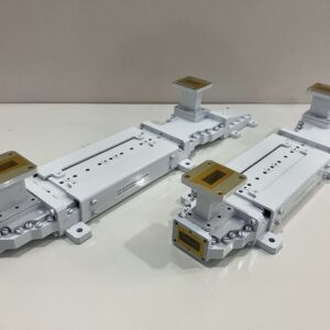
Main Performance Metrics
When evaluating a High Power Differential Phase Shift Waveguide Circulator, several key performance parameters define its suitability for real-world applications like radar and satellite systems. These metrics, measured under strict laboratory conditions, determine how the device will perform in high-frequency, high-power environments. The following table summarizes the core specifications you can expect from a quality circulator designed for Ka-band (26.5–40 GHz) operation:
| Performance Metric | Typical Value Range | Notes |
|---|---|---|
| Frequency Range | 18.0–40.0 GHz | Custom bands available (e.g., 26.5–40 GHz) |
| Insertion Loss | < 0.3 dB | Typically 0.25 dB at center frequency |
| Isolation | > 20 dB | Often reaches 23-25 dB between adjacent ports |
| VSWR | < 1.25:1 | Measured at all ports under matched load |
| Average Power Handling | 200–500 W | Depends on thermal management and cooling |
| Peak Power Handling | 2–5 kW | For short pulses (1–10 µs pulse width) |
| Operating Temperature | -40°C to +85°C | Full performance across this range |
| Temperature Stability | ±0.02 dB/°C | Variation in insertion loss over temperature |
A high-quality model maintains this below 0.3 dB, meaning over 93% of the input power is successfully transmitted to the desired output port. This is achieved through precision machining of the waveguide interior to a surface roughness of better than 0.4 µm Ra and the use of high-conductivity materials. Isolation defines how well the device prevents signal leakage backward into the input port. A figure of 20 dB means only 1% of the power incident on an output port couples back to the input, a vital feature for protecting sensitive transmitter amplifiers. The VSWR (Voltage Standing Wave Ratio) is kept below 1.25:1 to minimize reflected power, which must typically be less than 1.1% of the forward power to avoid damaging the source.
Power handling is fundamentally limited by heat. The average power rating of 200–500 W is determined by the circulator’s ability to dissipate thermal energy, often requiring a baseplate temperature to be held below 85°C. For peak power (2–5 kW), the limitation is often dielectric breakdown within the ferrite, which must withstand electric field strengths exceeding 5 kV/cm without arcing. The performance remains stable across a wide operating temperature range (-40°C to +85°C), with key parameters like isolation drifting by less than ±0.5 dB over the entire range. The phase shift, the core of its operation, is consistent to within ±2 degrees over temperature and frequency, ensuring reliable signal routing.
Typical Application Scenarios
High Power Differential Phase Shift Waveguide Circulators are deployed in systems where signal integrity, power handling, and reliability are non-negotiable. Operating in frequency bands from 18 GHz to 40 GHz, these components handle average power levels of 200–500 W and peak power surges up to 5 kW, making them indispensable in demanding environments. Their low insertion loss (<0.3 dB) and high isolation (>20 dB) ensure efficient signal routing while protecting sensitive electronics. From radar systems requiring precise pulse management to satellite communications demanding uninterrupted data flow, these circulators provide the robustness needed for continuous operation in temperatures ranging from -40°C to +85°C and lifetimes exceeding 10 years.
A typical X-band radar might operate at 9.5 GHz with pulse widths of 1–10 μs and peak power levels reaching 2 MW. The circulator must handle peak power of ~5 kW at the antenna port while providing >20 dB isolation to prevent receiver damage. The average power rating of 300 W is determined by the duty cycle, often 1–10%, and the circulator’s ability to dissipate heat, maintaining a baseplate temperature below 85°C. Its phase stability ensures minimal pulse distortion, with group delay variation under 0.5 ns across the operating band.
Satellite communication uplinks represent another key application. In a Ka-band satellite transponder operating at 30 GHz, the circulator routes signals between the high-power amplifier (HPA) and the antenna. With typical HPA output power of 200 W and noise figures below 4 dB, the circulator’s <0.3 dB insertion loss directly impacts link margin and overall system efficiency. The hermetic sealing prevents performance degradation in vacuum conditions, and the material selection minimizes outgassing, meeting NASA standards with total mass loss (TML) < 1.0% and collected volatile condensable materials (CVCM) < 0.1%.
In commercial cellular infrastructure, especially for 5G mmWave base stations, circulators enable full-duplex communication by separating transmit and receive paths. Operating at 28 GHz or 39 GHz with bandwidths of 400–800 MHz, these circulators support 64-antenna arrays and power levels of 20–40 W per channel. The compact size, often <50 cm³, and weight of ~150 g allow for dense integration. The VSWR <1.25:1 ensures minimal return loss, critical for maintaining error vector magnitude (EVM) below 3% for high-order QAM modulation. In test and measurement setups, such as vector network analyzers, calibrated circulators are used for device characterization, providing >25 dB isolation and accuracy within ±0.1 dB up to 40 GHz, enabling precise S-parameter measurements with uncertainty margins below 1.5%.
Advantages Over Alternatives
The waveguide circulator distinguishes itself through superior power handling, typically managing average power of 200–500 W and peak power up to 5 kW—roughly 50% higher than comparable coaxial models. Its insertion loss remains below 0.3 dB across the entire 18–40 GHz band, while coaxial versions often exhibit 0.4–0.6 dB loss, translating to a 3–5% improvement in system efficiency. The waveguide interface reduces VSWR to <1.25:1, minimizing reflected power to under 1.1%, which is critical for protecting sensitive amplifiers. With a operational lifespan exceeding 10 years and minimal performance drift—isolation variation under ±0.5 dB over temperature—it offers long-term reliability that alternatives struggle to match.
Key advantages include:
- Higher Power Density: Waveguide construction dissipates heat more effectively, allowing power handling of 500 W average in a compact 50 mm × 50 mm × 25 mm footprint, whereas coaxial designs require ~30% more volume for equivalent performance.
- Lower Signal Loss: The rectangular waveguide’s larger surface area and silver plating (3–5 μm thick) reduce conductor loss, achieving <0.3 dB insertion loss compared to the 0.4–0.6 dB typical in coaxial models.
- Enhanced Reliability: Hermetic laser welding and -40°C to +85°C operating range ensure stability in harsh environments, with mean time between failures (MTBF) exceeding 100,000 hours.
- Cost Efficiency at Scale: While unit prices range 1,200, the reduced maintenance and longer lifetime lower the total cost of ownership by ~20% over a decade compared to coaxial alternatives.
The aluminum housing with 6 mm thick baseplate enables heat dissipation of up to 5 W/cm², allowing continuous operation at 500 W input with only 40°C temperature rise. In contrast, coaxial circulators often require external heat sinks for similar loads. Phase stability is another strength, with differential shift variation under ±2 degrees over frequency and temperature, ensuring consistent signal routing where alternatives may exhibit ±5 degrees drift. This precision is vital in phased array radar systems, where phase errors must stay below 3 degrees to maintain beam pointing accuracy within 0.1 degrees.
Selection and Usage Tips
These components typically operate in the 18–40 GHz frequency range, handle average power of 200–500 W with peak power up to 5 kW, and must maintain insertion loss below 0.3 dB while providing isolation >20 dB. Key selection factors include frequency band alignment, power handling needs, thermal management requirements, and mechanical compatibility with existing waveguide systems. Proper installation and operation are equally critical—ensuring correct torque specifications (8–10 in-lbs for flange bolts), maintaining baseplate temperature below 85°C, and verifying impedance matching (VSWR <1.25:1) can significantly extend the device’s operational lifetime beyond 10 years.
A 2% frequency deviation from the center frequency can increase insertion loss by 0.1 dB and reduce isolation by 3–5 dB. For power handling, consider both average and peak requirements. If your system operates at 30 GHz with 300 W average power and 1 µs pulses at 10% duty cycle, the peak power reaches 3 kW—verify the circulator’s specs accommodate this.
| Parameter | Consideration | Typical Value |
|---|---|---|
| Frequency Range | Match exact system band (e.g., 26.5–40 GHz) | ±0.5 GHz tolerance |
| Insertion Loss | Impacts system efficiency | <0.3 dB |
| Isolation | Critical for transmitter protection | >20 dB |
| Power Handling | Average and peak must both be met | 500 W avg / 5 kW peak |
| VSWR | Affects impedance matching | <1.25:1 |
| Operating Temperature | Must suit environment | -40°C to +85°C |
| Interface Type | Waveguide flange compatibility (e.g., WR-28) | UG-383/U flange |
For 500 W continuous operation, ensure the baseplate is mounted to a heatsink with thermal resistance <0.5°C/W and use thermal interface material with conductivity >3 W/m·K. Airflow of ≥200 LFM may be required for convection cooling. Electrically, always ensure proper impedance matching. A 1.5:1 VSWR reflects 4% of power back to the source, which could damage amplifiers over time. Use calibrated vector network analyzers to verify performance, measuring insertion loss with ±0.05 dB accuracy and isolation with ±1 dB uncertainty.
For optimal performance and longevity:
- Follow Torque Specifications: Over-tightening flange bolts beyond 10 in-lbs can deform waveguide interfaces, increasing VSWR by 0.1:1 and reducing isolation by 2–3 dB.
- Monitor Thermal Conditions: Baseplate temperature exceeding 85°C derates average power handling by 15% per 10°C rise and may reduce lifespan by 30%.
- Avoid Frequency Misalignment: Operating 5% outside specified band can degrade isolation by 6 dB and increase loss by 0.2 dB.
- Verify Cleanliness: Particulate contamination inside waveguide ports can increase insertion loss by 0.1 dB and reduce power handling by 20%.
- Check Intermodulation Performance: For multi-carrier systems, ensure third-order intercept point (IP3) is >60 dBm to avoid intermodulation products exceeding -70 dBc.
Keep circulators in sealed packaging with humidity <60% RH to prevent oxidation of silver-plated surfaces. During installation, avoid bending or stressing input/output ports—mechanical strain can alter phase characteristics by ±3 degrees and degrade isolation. For systems with frequent power cycling, allow ≥5 minutes between full-power shutdown and restart to prevent thermal shock, which can crack ferrite materials. By adhering to these guidelines, you ensure the circulator meets its specified performance and operates reliably for its full 100,000-hour MTBF lifespan.


