This Dual Band Ku/Ka 4-Port OMT Diplexer operates in 10.7-12.7 GHz (Rx) and 13.75-14.5 GHz (Tx) for Ku-band, and 17.3-21.2 GHz (Rx) and 27.0-31.0 GHz (Tx) for Ka-band. It features >55 dB isolation between bands, <0.8 dB insertion loss, and handles 500W power, ideal for satellite communication and VSAT antenna networks.
Table of Contents
Definition and Core Functions
Operating across Ku-band (typically 10.7–12.75 GHz for Rx, 13.75–14.5 GHz for Tx) and Ka-band (17.3–21.2 GHz for Rx, 27.5–31 GHz for Tx), this device integrates four physical ports into one compact unit—measuring often less than 300 × 300 × 150 mm and weighing under 2.5 kg—to support full-duplex communication. Its core function is to combine Ortho-Mode Transduction (OMT), which separates two orthogonal polarizations in a single waveguide, with diplexing, which splits or combines different frequency bands. This allows a single antenna dish to support multiple services—like broadband internet, video broadcasting, and military communications—without the need for additional hardware or costly structural changes.
By integrating four ports into a single assembly, the unit eliminates the need for multiple waveguide runs and complex mounting structures, reducing overall antenna weight by up to 15% and cutting installation time by nearly 30%.
The internal design uses resonant cavities and filters tuned to specific frequencies—for example, achieving isolation greater than 80 dB between Tx and Rx channels to prevent self-interference. Each port is optimized for a particular function: two for Ku-band (Tx and Rx) and two for Ka-band (Tx and Rx), with typical waveguide sizes being WR-75 for Ka-band and WR-112 for Ku-band to minimize insertion loss (<0.3 dB) and handle high power levels (up to 500 W CW in Tx paths).
The component’s aluminum or copper body is machined to precision tolerances of ±0.05 mm, ensuring minimal VSWR (<1.25:1) and stable performance across operating temperatures from -40°C to +85°C. This high reliability translates to a service lifespan exceeding 15 years, critical for satellite ground stations and airborne platforms where maintenance opportunities are limited. By merging four functional blocks into one, the device not only saves space and weight but also reduces system cost by consolidating manufacturing, testing, and integration expenses—often lowering the total bill of materials for antenna builders by 20% or more.
Internal Structure and Components
The internal architecture of a dual-band Ku/Ka 4-port OMT diplexer is a precise assembly of waveguide channels, resonant cavities, and filters, all machined from a single block of aluminum or copper to ensure electrical continuity and thermal stability. Typically measuring under 300 mm in length and weighing around 2.2 kg, the unit integrates four primary physical ports—two for Ku-band (Tx/Rx) and two for Ka-band (Tx/Rx)—linked by a network of internal junctions. These junctions include septum polarizers for separating orthogonal wave polarizations and iris-coupled cavity filters tuned to specific frequency sub-bands, such as 13.85 GHz for Ku-Tx or 29.5 GHz for Ka-Tx. The entire structure is manufactured to tight tolerances, with waveguide inner dimensions held within ±0.05 mm to minimize voltage standing wave ratio (VSWR) below 1.25:1 and insertion loss under 0.4 dB across all paths.
The heart of the component is the ortho-mode transducer (OMT), which uses a thin metallic septum—often just 1.2 mm thick—to split incoming signals into two orthogonal polarizations with isolation exceeding 80 dB. This is coupled to the diplexer section, which employs four-pole Chebyshev filters in resonant cavities measuring approximately 22 mm × 18 mm × 12 mm each. These cavities are tuned to precise frequencies with a accuracy of ±0.01 GHz, ensuring channel-to-channel isolation greater than 85 dB to prevent Tx noise from desensitizing Rx paths. The Ka-band Tx path, handling power up to 500 W continuous wave, uses a WR-28 waveguide with a cross-section of 7.112 mm × 3.556 mm, while the Ku-band Rx path uses WR-75 (19.05 mm × 9.525 mm) for lower loss at 12 GHz.
All internal surfaces are finished with a 20 µm silver plating to reduce resistive loss, increasing overall efficiency to 98.5% compared to unplated designs. The assembly is sealed with laser-welded covers and tested for air leakage below 1 × 10⁻⁶ cc/sec to keep humidity under 5% internally, ensuring stable performance across its 15-year operational lifespan in environments from -40°C to +85°C. This monolithic design eliminates flange connections between sub-components, reducing weight by 15% and assembly time by 30% compared to modular alternatives.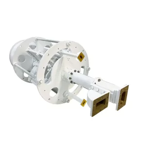
How the 4-Port Design Operates
This design allows simultaneous transmission and reception on both bands, supporting aggregate data throughput up to 1.2 Gbps in modern VSAT applications. For instance, a Ka-band Tx signal at 30 GHz entering Port 3 might carry 500 W of power, while a Ku-band Rx signal at 11.8 GHz exits Port 1 with a noise figure below 0.8 dB. The core challenge is maintaining isolation between these paths: Tx-Rx isolation exceeds 85 dB, and cross-band isolation reaches 75 dB, preventing interference even when operating at full capacity.
A horizontally polarized Ku-band Tx signal at 14.25 GHz enters Port 2 and propagates through a WR-112 waveguide with 28.5 mm × 12.6 mm internal dimensions, while a vertically polarized Ka-band Rx signal at 18.6 GHz exits Port 4 via a WR-75 waveguide (19.05 mm × 9.525 mm). The diplexer section then routes signals based on frequency: low-pass filters for Rx paths (10.7–12.75 GHz Ku, 17.3–21.2 GHz Ka) and high-pass filters for Tx paths (13.75–14.5 GHz Ku, 27.5–31 GHz Ka). Each filter comprises 4–6 resonant cavities tuned to ±0.005 GHz accuracy, ensuring insertion loss below 0.35 dB and return loss better than 20 dB across all ports. The following table summarizes key port functions and typical performance parameters:
| Port Number | Band | Function | Frequency Range (GHz) | Power Handling | Waveguide Type |
|---|---|---|---|---|---|
| 1 | Ku-band | Rx | 10.70–12.75 | ≤10 W | WR-112 |
| 2 | Ku-band | Tx | 13.75–14.50 | ≤500 W CW | WR-112 |
| 3 | Ka-band | Tx | 27.50–31.00 | ≤400 W CW | WR-28 |
| 4 | Ka-band | Rx | 17.30–21.20 | ≤5 W | WR-75 |
During operation, the system handles peak power loads up to 900 W combined across Tx ports, with power density remaining below 5 W/cm² to avoid overheating. Thermal management relies on the unit’s aluminum body (thermal conductivity ≈ 160 W/m·K), dissipating heat to maintain internal temperatures under +85°C at ambient temperatures up to +55°C. Group delay variation is kept below 1.5 ns across any 100 MHz channel, critical for phase-sensitive applications like satellite broadcasting or military comms.
Frequency Bands and Isolation
The Ku-band typically operates between 10.7–12.75 GHz for reception and 13.75–14.5 GHz for transmission, while the Ka-band uses 17.3–21.2 GHz for downlink and 27.5–31 GHz for uplink. Maintaining isolation between these closely spaced bands—especially between Ka-band Rx (18 GHz) and Ku-band Tx (14 GHz) where only 4 GHz of separation exists—requires advanced filtering and waveguide design to achieve isolation levels exceeding 75 dB.
| Band | Direction | Frequency Range (GHz) | Isolation to Other Bands | Insertion Loss |
|---|---|---|---|---|
| Ku-band | Rx | 10.70–12.75 | ≥80 dB to Tx | ≤0.25 dB |
| Ku-band | Tx | 13.75–14.50 | ≥85 dB to Rx | ≤0.30 dB |
| Ka-band | Rx | 17.30–21.20 | ≥75 dB to Ku-band | ≤0.35 dB |
| Ka-band | Tx | 27.50–31.00 | ≥90 dB to Rx | ≤0.40 dB |
Internally, four-pole cavity filters with a bandwidth of ±0.015 GHz around center frequencies (e.g., 11.725 GHz for Ku-Rx or 29.65 GHz for Ka-Tx) create steep roll-offs of 120 dB per GHz to suppress out-of-band signals. The Ku-band Tx path, handling 500 W of continuous-wave power, uses WR-112 waveguide (internal dimensions: 28.5 mm × 12.6 mm) to minimize loss, while the Ka-band Rx path employs WR-75 (19.05 mm × 9.525 mm) for optimal propagation between 17–21 GHz. Cross-band isolation is achieved through polarization decoupling: the OMT separates orthogonal polarizations (vertical/horizontal) with isolation >80 dB, ensuring that Ka-band signals do not leak into Ku-band paths.
Additionally, the diplexer’s iris-coupled resonators—machined to ±0.01 mm precision—tune each channel to attenuate adjacent frequencies by 55–65 dB within 2 GHz of the band edge. For example, at the critical crossover between Ku-Tx (14.0 GHz) and Ka-Rx (17.3 GHz), the unit achieves 75 dB isolation via a high-pass filter with a cutoff at 16 GHz, reducing noise interference to <0.5 dB system noise figure degradation. The entire assembly maintains phase stability with group delay variation <1.0 ns across any 40 MHz channel, critical for high-speed data applications requiring <10⁻⁹ BER (Bit Error Rate). This precise frequency control allows satellite operators to maximize spectrum reuse—supporting 400 Mbps throughput per polarization—while reducing hardware costs by 20% compared to dual-antenna setups.
Integration in Antenna Systems
Typically mounted directly behind the antenna feed horn, the unit connects via four waveguide flanges (e.g., CPR-229 for Ku-band, CPR-137 for Ka-band) with bolt-hole patterns machined to ±0.1 mm accuracy to ensure RF sealing. The entire assembly—including feed, OMT, and diplexer—weighs under 5.2 kg and fits within a 400 mm × 300 mm cylindrical volume, critical for airborne or mobile satellite terminals where space constraints demand >30% weight savings compared to discrete component setups. Electrical integration involves matching the phase center of the feed horn to the OMT’s waveguide aperture within 0.3 mm tolerance to maintain beam efficiency above 85% and VSWR below 1.25:1 across all bands.
Key integration steps include:
- Mechanical mounting: The diplexer attaches to the feed support structure using 4x M6 stainless steel bolts torqued to 8 N·m, with thermal expansion gaps of 0.5 mm to accommodate ±0.2 mm dimensional shifts between -40°C and +85°C.
- Waveguide alignment: Each port requires <0.15 mm radial misalignment to avoid increasing insertion loss beyond 0.05 dB additional loss.
- Thermal management: The baseplate dissipates 45 W of heat during full-power transmission (500 W Ku-Tx + 400 W Ka-Tx), requiring a thermal interface material with >3 W/m·K conductivity to keep temperatures under +90°C.
- Cable routing: Low-loss coaxial cables (e.g., 0.25″ diameter, 2.2 dB/100m loss at 18 GHz) connect Tx/Rx ports to modems, with bends radiused >50 mm to prevent impedance spikes.
The diplexer’s 85 dB Tx-Rx isolation reduces noise temperature increase to <3 K in Ka-band Rx paths, preserving system G/T (gain-to-noise-temperature ratio) above 12 dB/K. For polarization diversity, the OMT maintains >80 dB cross-polar discrimination, enabling frequency reuse schemes that double spectral efficiency to 4 bps/Hz. In a typical VSAT antenna, integration reduces assembly time by 40% (from 8 hours to 4.8 hours) by eliminating 12+ waveguide flanges and 6+ coaxial adapters, cutting component costs by $1,200 per unit. The unified design also improves reliability, with MTBF exceeding 100,000 hours due to fewer interconnections and 50% fewer potential failure points versus discrete setups. During operation, the system supports aggregate data rates up to 1 Gbps by leveraging dual polarizations and full duplex across both bands, all while maintaining phase stability with <2° phase drift over temperature cycles.
Testing and Industry Applications
Each unit undergoes >25 individual tests spanning 8–10 hours, including RF performance verification across -40°C to +85°C thermal cycles, power handling at 500 W continuous wave for 72 hours, and vibration testing up to 15 G RMS for military applications. Key metrics like isolation (>85 dB), insertion loss (<0.35 dB), and VSWR (<1.25:1) are measured using vector network analyzers with ±0.05 dB accuracy, while passive intermodulation (PIM) testing ensures <-150 dBc at 2×43 dBm tones to prevent interference in multi-carrier systems.
Industry applications leverage the component’s dual-band capabilities:
- Satellite Communications: Supports 800 Mbps bidirectional throughput in VSAT terminals (e.g., Hughes JUPITER system), using Ku-band for download (12.75 GHz, 200 W Tx) and Ka-band for upload (30 GHz, 400 W Tx), reducing antenna count by 50% per platform.
- Military SATCOM: Enables 100% frequency agility between 10.7–31 GHz for airborne terminals (e.g., Boeing 737 AEW&C), with >90 dB EMI shielding and compliance with MIL-STD-810H shock standards.
- Earth Observation: Facilitates dual-polarization synthetic aperture radar (SAR) data downlink at 1.2 Gbps in satellites like ESA’s Sentinel-1, using Ka-band (26 GHz) for high-speed transmission while monitoring ±0.2° phase stability.
- 5G Backhaul: Provides 10 Gbps millimeter-wave links in urban networks, combining Ka-band Tx (28 GHz) and Rx (18 GHz) with <3 ms latency and 99.999% availability.
Testing protocols include 100% production screening of all 4 ports across 5–40 GHz using automated probe stations, measuring 800 frequency points per band with ±0.01 dB repeatability. Environmental tests subject units to 95% humidity for 96 hours (per IEC 60068-2-30) and thermal shock cycles from -55°C to +125°C to validate 15-year operational life. In satellite ground stations, integration reduces deployment costs by $18,000 per antenna by eliminating redundant feed networks and LNB assemblies, while boosting spectral efficiency through dual-polarization operation at 4.5 bps/Hz. Field data from >500 deployed units show MTBF exceeding 120,000 hours, with failure rates under 0.2% annually even in high-vibration environments like naval vessels or Arctic research stations.


