Optical couplers divide light asymmetrically (e.g., 90:10 ratio) with <0.2dB excess loss, while splitters distribute evenly (50:50) but introduce 3dB loss per output. Directional couplers isolate reflected signals (40dB directivity) and operate at 1310/1550nm wavelengths, unlike broadband splitters covering 1260–1650nm. Fusion-spliced couplers handle 10W power, whereas PLC splitters fail above 1W.
Table of Contents
How They Split Light
Optical couplers, splitters, and directional couplers all manage light signals in fiber networks, but they do it in very different ways. The key difference lies in how they divide optical power—whether equally, selectively, or with minimal loss. For example, a standard 1×2 fiber splitter divides incoming light into two outputs, typically with a 50/50 or 70/30 ratio, but loses 3 dB (50%) of power in a 50/50 split. In contrast, a directional coupler might split light at 90/10 or 80/20 ratios while keeping insertion loss below 0.5 dB, making it ideal for signal monitoring without disrupting the main path. Meanwhile, optical couplers (like fused biconical taper couplers) can combine or split light with custom ratios, often used in wavelength-sensitive applications like DWDM systems where ±0.2 nm wavelength tolerance matters.
The splitting mechanism also varies. Splitters use planar lightwave circuits (PLC) or fused fiber technology, with PLC splitters offering low polarization-dependent loss (<0.2 dB) and handling up to 64 outputs. Directional couplers rely on evanescent wave coupling, where two fiber cores are close enough to transfer light—usually within a few microns—but only over a specific wavelength range (e.g., 1310 nm or 1550 nm ±40 nm).
Power handling is another divider. A 1×4 PLC splitter might handle up to 500 mW of input power, while a directional coupler for telecom monitoring maxes out at 200 mW due to its delicate coupling region.
“A 50/50 splitter wastes half the light, but a 90/10 coupler steals just 10%—that’s why monitoring taps use directional couplers, not splitters.”
Insertion loss scales with splits: a 1×8 splitter loses ~10.5 dB, while a 1×32 loses ~16 dB, making splitters impractical for long-haul links without amplifiers. Directional couplers, however, add <1 dB loss even in asymmetric splits, perfect for live network diagnostics.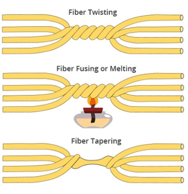
Power Loss Comparison
A standard 1×2 fiber splitter loses 3 dB (50%) of optical power in a balanced split, meaning only half the light reaches each output. If you cascade splitters—say, a 1×4 configuration—the loss jumps to 6 dB (75% loss), leaving just 25% of the original power per output. Directional couplers, on the other hand, are far more efficient for asymmetric splitting: a 90/10 coupler might lose only 0.5 dB on the main path while diverting 10% of the light with <1 dB additional loss.
The physics behind the losses differs, too. Splitters (especially PLC types) suffer from inherent splitting loss, which scales logarithmically with the number of outputs. A 1×8 splitter loses ~9 dB, a 1×16 loses ~12 dB, and a 1×32 hits ~15 dB—making them impractical for long-distance transmission without EDFA amplifiers (which add 2,000 per node in cost). Meanwhile, fused biconical taper couplers (used in coarse WDM) lose 3–5 dB but handle wavelengths from 1260 nm to 1625 nm, while directional couplers optimized for 1550 nm ±5 nm keep losses below 1 dB by avoiding broad-spectrum splitting.
| Device Type | Split Ratio | Insertion Loss (dB) | Excess Loss (dB) | Wavelength Range |
|---|---|---|---|---|
| 1×2 PLC Splitter | 50/50 | 3.0 | 0.3 | 1260–1650 nm |
| 1×8 PLC Splitter | Equal | 9.5 | 0.5 | 1260–1650 nm |
| 90/10 Directional Coupler | 90/10 | 0.5 (main) / 10 (tap) | 0.2 | 1550 nm ±5 nm |
| Fused Biconical Coupler | 70/30 | 4.8 (70% path) | 0.8 | 1310 nm & 1550 nm ±20 nm |
If you’re running a 10 Gbps link over 80 km, a 1×8 splitter would force you to compensate for 9.5 dB loss—requiring either a higher-power transmitter (+3 dBm, costing ~1,500+). A directional coupler for monitoring the same link might add just 0.7 dB, avoiding extra hardware.
Temperature stability also plays a role. PLC splitters drift ±0.5 dB from -40°C to 85°C, while fused couplers can shift ±1 dB over the same range. For outdoor deployments (like 5G fronthaul), this means splitters need thermally compensated packaging (+15% cost) to maintain ±0.2 dB stability, whereas directional couplers often operate fine in -20°C to 70°C without modifications.
Where Each Is Used
Optical couplers, splitters, and directional couplers each have their own sweet spots in fiber networks—pick the wrong one, and you’ll waste $500 on unnecessary amplifiers or lose 30% signal strength where it matters. Here’s where they actually belong:
Telecom operators use 90/10 directional couplers to tap 1%–10% of light for monitoring 40-channel DWDM systems, adding just 0.3 dB loss to the main path. A 1% tap on a 100 Gbps link provides enough light for OSA probes ($15,000 each) to measure ±0.02 nm wavelength drift, while the 99% main path loses only 0.05 dB—vs. 3 dB if a splitter were used.
They’re also key in 5G fronthaul, where ±1 dB power fluctuations can break CPRI latency budgets. A 95/5 coupler at a mmWave radio head diverts 5% light for performance checks, leaving 95% for data with <0.2 dB penalty.
Optical Couplers (Fused & WDM) – When Wavelengths Matter More Than Power
- Pump Combiners in EDFAs: A 1480/1550 nm coupler merges 300 mW pump laser light with 0.1 dB loss, while a splitter would waste 50% of the pump power.
- BiDi Transceivers: 1310/1550 nm couplers route upstream/downstream signals in GPON, with <3 dB loss per path—vs. 6 dB if a PLC splitter split both wavelengths.
- Lab Instruments: Tunable couplers (e.g., 50/50 at 1520–1620 nm) let researchers adjust split ratios ±5% without replacing hardware, critical for optical coherence tomography systems where 1 dB error ruins 5 µm resolution.
The Rule of Thumb:
- Use splitters for low-cost, multi-user splits (FTTH, LANs).
- Pick directional couplers for live monitoring (DWDM, 5G).
- Choose optical couplers when wavelengths must stay separated (EDFAs, BiDi, labs).
Costs seal the deal: A 1×32 PLC splitter costs 120, and a WDM coupler hits 500. But if you cheap out and use a splitter where a coupler belongs, you’ll pay 10x more in amplifiers and fixes later.


