Near-field measurements analyze antenna patterns within 1-2 wavelengths (λ) using probes, capturing detailed phase/amplitude data for simulations, while far-field tests (beyond 2λ²/λ) assess radiation efficiency in open ranges or anechoic chambers. Near-field requires precise positioning (±1mm accuracy), whereas far-field needs 10+ meters of clearance. Convert near-field data via Fourier transforms for far-field predictions.
Table of Contents
Distance and Signal Strength
Antenna measurements depend heavily on whether you’re testing in the near-field (close to the antenna) or far-field (far enough for stable wave propagation). The key difference lies in distance and how it impacts signal strength, phase, and radiation patterns.
In near-field measurements, the test distance is typically less than 2D²/λ, where D is the antenna’s largest dimension and λ is the wavelength. For example, a 5 GHz Wi-Fi antenna with a 10 cm aperture requires measurements within 33 cm to stay in the near-field. Signal strength here drops rapidly—often -20 dB per decade—due to reactive fields dominating.
Far-field measurements start at ≥2D²/λ, where the signal follows inverse-square law (-6 dB per doubling of distance). A 1W transmitter at 10 meters might measure -30 dBm, but at 20 meters, it drops to -36 dBm. Phase variations also stabilize in far-field, with <1° error per wavelength, making it ideal for radiation pattern analysis.
| Parameter | Near-Field | Far-Field |
|---|---|---|
| Distance | <2D²/λ (e.g., 33 cm for 5 GHz, 10 cm antenna) | ≥2D²/λ (e.g., >33 cm for same antenna) |
| Signal Decay | -20 dB/decade (reactive fields) | -6 dB/doubling (radiative fields) |
| Phase Stability | High variation (up to ±180° near aperture) | Stable (<1° error per λ) |
| Use Case | Precise diagnostics, beamforming tuning | Radiation patterns, regulatory compliance |
Near-field scanning is 10-50x more expensive due to robotic probes and complex software, while far-field ranges use simpler setups like open-area test sites (OATS) or anechoic chambers. However, near-field captures microwave/mmWave beam shapes with ±0.5 dB accuracy, critical for 5G phased arrays.
For low-frequency antennas (e.g., 100 MHz), the far-field distance balloons to 40 meters for a 2m antenna, making near-field the only practical option. In contrast, 60 GHz antennas reach far-field in just 4 cm, simplifying testing.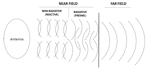
Measurement Setup Differences
Near-field and far-field antenna testing require completely different hardware, software, and environmental conditions. The biggest factor? Distance—but that’s just the start. Near-field setups demand precision robotics, calibrated probes, and shielded chambers, while far-field relies on open spaces, high-gain reference antennas, and minimal reflections.
A typical near-field scanner uses a robotic arm with ±0.1 mm positioning accuracy to move a probe across the antenna’s surface at 5-20 cm intervals, capturing electric (E-field) and magnetic (H-field) data at 1,000+ sample points. The chamber must suppress reflections by ≥60 dB, requiring ferrite tiles and pyramidal absorbers costing 1,000 per square meter.
”Near-field testing is like MRI scanning—you need millimeter-level control. Far-field is more like a telescope—you just need clear line-of-sight.”
Far-field setups, on the other hand, often use anechoic chambers (10m x 10m x 10m for sub-6 GHz) or outdoor test ranges (100m+ for low frequencies). The reference antenna must have ≥10 dB higher gain than the device under test (DUT) to minimize measurement errors. For 28 GHz 5G antennas, a standard horn antenna with 20 dBi gain works, but at 600 MHz, you’d need a large log-periodic array (5m wide, $15k+).
Software processing is another key difference. Near-field systems use Fourier transforms to convert sampled data into far-field patterns, adding 3-5% computational error. Far-field measurements skip this step, but multipath interference can distort results by ±2 dB if the ground reflection isn’t suppressed.
Cost-wise, near-field setups run 1M+ due to robotic arms and absorbers, while far-field ranges can be <$50k if using an open field. But mmWave antennas (24-100 GHz) flip this—their tiny far-field distance (as low as 30 cm) means compact chambers work, cutting costs.
Data Processing Methods
When it comes to antenna measurements, raw data is useless without proper processing—and near-field vs. far-field methods couldn’t be more different. Near-field measurements spit out gigabytes of complex E/H-field samples that need Fourier transforms, probe correction, and phase unwrapping, while far-field data is simpler but highly sensitive to noise and reflections.
Near-field processing starts with sampling density—you need at least 5 points per wavelength (λ) to avoid aliasing. For a 28 GHz antenna, that means 1.4 mm spacing between probe positions. Miss this, and your beamwidth calculation error jumps from ±0.5° to ±3°. The raw data then goes through spherical wave expansion (SWE), which converts near-field scans into far-field patterns with 85-95% accuracy depending on algorithm choice.
Far-field measurements skip the heavy math but face environmental errors. A 2° misalignment between the test antenna and reference horn can cause ±1.5 dB gain errors. Ground reflections add another ±3 dB ripple at 1-3 GHz frequencies unless you use time-domain gating to filter them out. For polarization purity tests, you’re dealing with cross-polarization levels below -25 dB, meaning your processing must reject 0.1% noise contamination just to stay accurate.
Computational load varies wildly. Near-field processing for a 256-element phased array at 60 GHz takes 8-12 hours on a 32-core workstation, mostly spent on matrix inversions. Far-field post-processing is faster (under 1 minute per frequency point) but requires 10-20 averages to suppress noise, stretching test time.
Calibration errors compound differently. Near-field systems suffer from ±0.3 dB probe positioning errors, while far-field setups battle ±1 dB system gain drift over 8-hour tests. If you’re measuring antenna efficiency, a 2% error in near-field data can mean 5-8% wrong efficiency values due to integration math.
Common Use Cases
Choosing between near-field and far-field antenna testing isn’t about which is “better”—it’s about which solves your specific problem faster, cheaper, and more accurately. Near-field dominates when you need microwave-level precision on small antennas, while far-field excels at real-world performance validation of large systems.
For 5G mmWave phased arrays (24-100 GHz), near-field is the only practical choice because the far-field distance shrinks to just 4-30 cm. Automotive radar antennas at 77 GHz are tested this way, with robotic scanners capturing ±0.5 dB beam patterns across 256 elements in under 2 hours. Satellite communications dishes (1-2m diameter, 12-18 GHz) also use near-field to verify surface deformations as small as 0.1mm that could cause 3dB sidelobe degradation.
Far-field testing rules for cellular base station antennas (600MHz-6GHz) where the far-field distance ranges 5-50m. Telecom operators validate sector coverage patterns in open-air ranges, measuring 65° horizontal beamwidths with ±1° accuracy. WiFi routers (2.4/5GHz) typically skip near-field because their omnidirectional patterns only need far-field verification of <3dB ripple across 360°.
| Antenna Type | Frequency | Best Method | Key Measurement | Tolerance | Test Time |
|---|---|---|---|---|---|
| 5G mmWave Array | 28/39GHz | Near-field | Beam steering ±30° | ±0.5dB gain | 1-3 hrs |
| Satellite Dish | 12-18GHz | Near-field | Surface accuracy | 0.1mm RMS | 4-8 hrs |
| Cellular Macro BS | 700MHz-3.5GHz | Far-field | 65° HPBW | ±1° | 30 min |
| WiFi Omni | 2.4/5GHz | Far-field | 360° coverage | <3dB ripple | 15 min |
| Automotive Radar | 77GHz | Near-field | 256-element phase | ±2° | 2 hrs |
Cost and logistics drive many decisions. Near-field requires $500k+ chambers but saves money on 60GHz antennas where far-field distances are trivial. Far-field wins for sub-6GHz massive MIMO because building a 50m near-field range would be absurd. Military radars use hybrid approaches—near-field for AESA calibration followed by far-field range validation at 10km distances.
Emerging tech is blurring the lines. Compact antenna test ranges (CATR) now simulate far-field conditions in 5m chambers using parabolic reflectors, cutting test time by 60% for 28GHz beamforming arrays. Meanwhile, drones with RF probes enable rapid far-field checks of airborne antennas that previously required costly towers.


