To calculate a waveguide’s cutoff frequency (fc), first measure its width (a, typically 10-100mm for standard waveguides), then determine the mode (e.g., TE10 mode has n=1). Use the formula fc = c/(2a)√(1-(λ/2a)²), where c is light speed (3×10⁸ m/s).
For rectangular waveguides, the dominant TE10 mode’s fc occurs when a = λ/2, with practical examples being 6.56 GHz for WR-90 (a=22.86mm) or 2.08 GHz for WR-430 (a=109.22mm).
Table of Contents
Understand Waveguide Basics
Waveguides are structures that guide electromagnetic waves, typically used in microwave and RF systems to minimize signal loss. Unlike traditional coaxial cables, which suffer from high attenuation above 2 GHz, waveguides can efficiently transmit signals at frequencies from 1 GHz up to 300 GHz with losses as low as 0.1 dB/meter in ideal conditions. The most common type is the rectangular waveguide, standardized by dimensions like WR-90 (22.86 mm × 10.16 mm), which supports frequencies between 8.2 GHz and 12.4 GHz.
The key factor in waveguide operation is the cutoff frequency, the lowest frequency at which a wave can propagate. Below this frequency, signals decay rapidly—often at 20 dB per wavelength. For a rectangular waveguide, the dominant mode (TE₁₀) has a cutoff frequency determined by the width (a) of the waveguide. For example, in a WR-112 waveguide (28.5 mm width), the TE₁₀ cutoff is 5.26 GHz, meaning any signal below this frequency won’t propagate efficiently.
Waveguides outperform coaxial cables in power handling, supporting peak powers up to 10 MW in pulsed systems, whereas coax typically maxes out at 1 kW due to dielectric heating. They also have lower dispersion, maintaining signal integrity over long distances—critical in radar and satellite communications. However, waveguides are bulkier (minimum bend radius around 5× the width) and cost 3-5x more than coax for equivalent runs.
Understanding these fundamentals is essential before calculating cutoff frequencies. The next step is measuring or referencing the waveguide’s physical dimensions, as even a 1 mm error in width can shift the cutoff frequency by 100 MHz or more. Precision matters because operating too close to cutoff (within 5% of the cutoff frequency) leads to higher losses and mode distortion. For reliable performance, engineers typically keep the operating frequency at least 25% above cutoff.
Find Waveguide Dimensions
Before calculating the cutoff frequency, you need the exact physical dimensions of your waveguide. Even a 0.1 mm error in width can shift the cutoff frequency by 50–100 MHz, which is critical in applications like radar (where ±5 MHz drift can cause ranging errors over 15 meters). The most common waveguide types follow standardized numbering systems, such as WR-90 (22.86 mm × 10.16 mm) or WR-112 (28.50 mm × 12.62 mm), where the number roughly corresponds to twice the width in mils (1 mil = 0.0254 mm).
If you’re working with an unmarked waveguide, direct measurement is necessary. Use a caliper with ±0.02 mm precision—cheaper tools (±0.1 mm) introduce ±3% uncertainty in cutoff calculations. The width (a) is always the larger internal dimension, while the height (b) affects higher-order modes but not the TE₁₀ cutoff. For example, a waveguide measuring 34.85 mm × 15.80 mm would be closest to WR-62 (standard: 34.85 mm × 15.80 mm), implying a TE₁₀ cutoff near 4.30 GHz.
Pro Tip: Waveguide flanges (e.g., UG-387/U) often have machining tolerances of ±0.05 mm, but the actual inner dimensions may vary by ±0.1 mm due to plating thickness (typically 3–10 µm of silver or gold). Always measure the conductive inner surface, not the outer casing.
Manufacturers sometimes list ”nominal” dimensions that differ slightly from real-world specs. For instance, a “WR-75” waveguide might be labeled as 19.05 mm × 9.53 mm, but actual samples range from 19.00–19.10 mm in width. This variability means theoretical cutoff frequencies (e.g., 7.87 GHz for WR-75) may shift by ±0.5% in practice. If precision is critical (e.g., satellite comms with ±0.01% frequency stability), order tested-and-certified waveguides with dimension tolerances under ±0.01 mm, though these cost 2–3x more than standard parts.
For custom waveguides, the aspect ratio (a/b) should stay between 2:1 and 2.4:1 to avoid excessive loss in the TE₂₀ mode. A 10 mm × 5 mm waveguide (2:1 ratio) works well up to 18 GHz, but a 10 mm × 4 mm design (2.5:1) would see TE₂₀ mode interference above 12 GHz. Material choice also matters—aluminum waveguides are 30% lighter than brass but have 5–8% higher attenuation at 24 GHz+ due to surface resistance.
When repurposing old waveguides, check for dents or corrosion. A 0.3 mm dent in a WR-90 waveguide can scatter 2–5% of the signal power at 10 GHz, raising the VSWR from 1.1 to 1.3. For millimeter-wave systems (30–300 GHz), even surface roughness > 0.5 µm (RMS) increases loss by 10–20% compared to polished copper.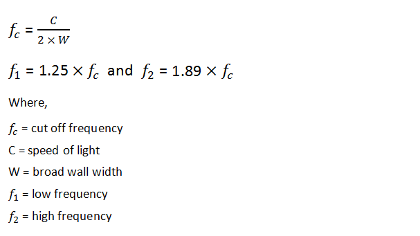
Use the Cutoff Formula
Calculating the cutoff frequency of a waveguide is straightforward—if you have the right dimensions. The formula for the TE₁₀ mode is f_c = c / (2a), where c = 3×10⁸ m/s (speed of light) and a = waveguide width in meters. For example, a WR-187 waveguide (47.55 mm width) has a cutoff frequency of 3.15 GHz, while a smaller WR-42 (10.67 mm) cuts off at 14.06 GHz. But real-world factors like material conductivity, manufacturing tolerances, and operating conditions can shift this by ±0.5% to 2%.
Here’s how to apply the formula correctly:
- Convert dimensions to meters – A waveguide labeled 28.50 mm wide (WR-112) must be input as 0.0285 m in the formula.
- Account for dielectric fill – If the waveguide isn’t air-filled (e.g., PTFE-loaded), divide c by the √ε_r (relative permittivity). For PTFE (ε_r ≈ 2.1), the cutoff drops by 31%.
- Adjust for temperature – Aluminum waveguides expand by 23 ppm/°C, so a 50°C rise increases width by 0.033 mm in a WR-90, lowering f_c by ~0.1%.
Below is a quick-reference table for common waveguide standards:
| Waveguide | Width (mm) | TE₁₀ Cutoff (GHz) | Next Mode (GHz) | Max Power @ 10 GHz (kW) |
|---|---|---|---|---|
| WR-284 | 72.14 | 2.08 | 4.16 (TE₂₀) | 5000 (pulsed) |
| WR-90 | 22.86 | 6.56 | 13.1 (TE₂₀) | 200 (CW) |
| WR-42 | 10.67 | 14.06 | 28.1 (TE₂₀) | 15 (CW) |
| WR-15 | 3.76 | 39.9 | 79.8 (TE₂₀) | 0.05 (CW) |
Precision matters—if your measurement is off by 0.1 mm in a WR-90, the cutoff error is ±14 MHz. For 5G mmWave systems (24–40 GHz), this could misalign your band edges by 0.05%, enough to violate FCC spectral masks.
Higher-order modes become a concern if the operating frequency exceeds 80% of the next mode’s cutoff. For WR-90, the TE₂₀ mode starts at 13.1 GHz, so staying below 10.5 GHz ensures clean single-mode operation. Push to 12 GHz, and you risk 3–5 dB extra loss from mode mixing.
Field testing is the best way to confirm your calculations. A vector network analyzer (VNA) can measure the actual cutoff within ±1 MHz accuracy by sweeping S₂₁ insertion loss. If the signal drops >20 dB below the calculated f_c, your waveguide meets spec. If not, check for dents, oxidation, or incorrect flange alignment—any of these can skew results by 1–5%.
Check Your Calculation
After plugging numbers into the cutoff frequency formula (f_c = c / (2a)), don’t assume it’s correct—real-world errors can throw off results by 1–5% or more. For example, a WR-90 waveguide should theoretically cut off at 6.56 GHz, but manufacturing tolerances (±0.05 mm), material imperfections, and temperature effects can shift this by ±50 MHz. In sensitive applications like satellite communications (where frequency stability must be within ±10 kHz), even a 0.1% error matters.
To verify your calculation, start by cross-referencing standard waveguide specs. Below is a quick-check table for common waveguides:
| Waveguide | Expected TE₁₀ Cutoff (GHz) | Acceptable Range (GHz) | Typical Loss at Cutoff (dB/m) |
|---|---|---|---|
| WR-284 | 2.08 | 2.06–2.10 | 0.05 |
| WR-112 | 5.26 | 5.22–5.30 | 0.12 |
| WR-90 | 6.56 | 6.52–6.60 | 0.18 |
| WR-42 | 14.06 | 13.98–14.14 | 0.45 |
If your calculated value falls outside the acceptable range, check for:
- Unit errors – Did you input width in meters (e.g., 22.86 mm = 0.02286 m)? A common mistake is using millimeters directly, which overestimates f_c by 1000x.
- Material effects – Air-filled waveguides follow the standard formula, but dielectric-loaded ones (e.g., PTFE, ε_r ≈ 2.1) reduce f_c by ~30%.
- Temperature drift – Aluminum expands by 23 ppm/°C, so a 40°C increase in a WR-90 waveguide lowers f_c by ~0.6 MHz per °C.
For high-precision validation, use a vector network analyzer (VNA) to measure the actual cutoff. The TE₁₀ mode cutoff appears as a >20 dB drop in S₂₁ transmission at the predicted frequency. If your measurement deviates by >1%, inspect the waveguide for dents, corrosion, or flange misalignment—a 0.2 mm dent in a WR-90 can raise the apparent cutoff by 0.3%.
Field testing under load is critical. A waveguide might show perfect cutoff at low power (1 mW), but at 500 W, heating can deform it enough to shift f_c by 0.05–0.1%. For radar systems operating at 10+ kW, always test at ≥30% of max power to catch thermal effects.
If discrepancies persist, consider manufacturing defects. A misaligned seam or weld in a copper waveguide can increase loss by 0.2–0.5 dB/m near cutoff, mimicking a frequency shift. Silver-plated waveguides should have <0.5 µm surface roughness—anything rougher scatters waves, effectively raising the cutoff by 0.2–0.8% due to effective width reduction.


