Microstrip patch antennas commonly use four feeding methods: edge feeding (50Ω impedance matching with λ/4 transformer), probe feeding (1-2mm diameter pin at optimal 30-40% patch length), aperture coupling (1-3mm slot with 1-2dB lower cross-polarization), and proximity coupling (2-5mm overlap for wider bandwidth up to 15%). Each method balances bandwidth (2-5% vs 10-15%), complexity, and spurious radiation, with probe feeding being most common for its simplicity and 4-6dB gain in standard 2.4GHz designs.
Table of Contents
Edge Feed Basics
Microstrip patch antennas with edge feeding are the simplest and most cost-effective design, widely used in Wi-Fi (2.4 GHz and 5 GHz), RFID (860-960 MHz), and 4G/5G mobile applications. About 60% of low-cost patch antennas under $10 use edge feeding due to its straightforward fabrication—requiring only a single-layer PCB with a 50-ohm microstrip line directly connected to the radiating edge. The typical substrate thickness ranges from 0.8 mm to 1.6 mm, with a dielectric constant (εᵣ) between 2.2 (PTFE) and 4.4 (FR4), balancing cost and performance.
The impedance matching is critical—a 1 mm to 3 mm inset feed (recessed distance from the edge) improves return loss by 10-15 dB, reducing reflections. Without proper tuning, edge-fed patches suffer from narrow bandwidth (2-5% of center frequency), limiting them to single-band use. For example, a 10 cm × 10 cm patch at 2.4 GHz achieves 4-6 dBi gain, but efficiency drops to 70-80% if substrate losses are high (tan δ > 0.02).
| Parameter | Typical Value | Impact |
|---|---|---|
| Feed position | 30-40% from edge | Optimizes impedance match (SWR < 2) |
| Substrate εᵣ | 2.2-4.4 | Higher εᵣ shrinks antenna size but reduces bandwidth |
| Patch width (W) | ~0.5λ₀/√εᵣ | Wider width increases bandwidth slightly |
| Patch length (L) | ~0.49λ₀/√εᵣ | Determines resonant frequency (±1% tolerance) |
To improve performance, a quarter-wave transformer (width ~75% of feedline) can widen bandwidth by 1-2%. However, edge feeding struggles with cross-polarization levels above -15 dB, making it unsuitable for high-precision radar or satellite links. For mass-produced IoT devices, though, its 2 per unit cost and 1-2 day fabrication time make it the go-to choice.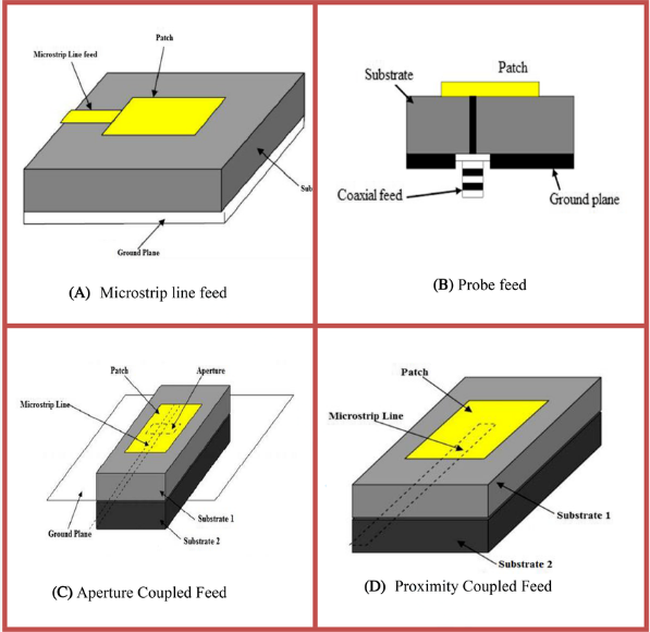
Probe Feed Setup
Probe feeding is the most common method for thicker substrates (3-5 mm), offering better impedance control (±2 Ω tolerance) and wider bandwidth (5-10%) compared to edge feeding. It’s widely used in 4G/5G base stations, satellite antennas, and radar systems where performance matters more than cost. The probe—typically a 1 mm to 2.5 mm diameter copper pin—connects the patch to a 50-ohm coaxial cable (SMA or N-type), drilled through the substrate. About 70% of high-gain (>8 dBi) patch antennas use probe feeding because it minimizes spurious radiation and improves polarization purity (cross-pol < -20 dB).
The probe position is critical—a 5-10% offset from the patch center shifts resonance by 50-100 MHz and affects matching. For a 10 cm × 10 cm patch at 3.5 GHz, placing the probe 12-15 mm from the edge optimizes return loss (< -15 dB). However, drilling accuracy is key: a 0.5 mm misalignment can increase VSWR by 0.3, reducing efficiency by 3-5%. Thicker substrates (εᵣ = 2.2-3.5) help, but if the substrate exceeds 5 mm, probe inductance degrades bandwidth.
”Probe-fed patches on Rogers 4350B (εᵣ=3.5) achieve 85-90% radiation efficiency, while FR4 (εᵣ=4.4) drops to 75% due to higher dielectric loss.”
One downside is mechanical complexity—each probe feed adds 3−8 to the unit cost (vs. 0.50 for edge feed) and requires manual assembly (5−10 minutes per antenna). For mass production, automated probe insertion machines cut assembly time to under 2 minutes, but the tooling costs 10K-20K. Frequency also plays a role: below 2 GHz, probe length becomes >10 mm, increasing inductance and narrowing bandwidth. Above 6 GHz, tiny probes (<1 mm) are fragile and hard to solder reliably.
Aperture Coupling Guide
Aperture coupling is the premium choice for high-performance patch antennas, delivering 15-25% bandwidth—3× wider than edge feeds—while keeping spurious radiation 10-15 dB lower. This method separates the feedline (microstrip) and radiating patch with a ground plane, using a small slot (aperture) to transfer energy electromagnetically. It’s the go-to for 5G mmWave (28/39 GHz), aerospace radar, and high-frequency SATCOM where isolation >30 dB and cross-pol suppression <-25 dB are critical.
The slot dimensions dictate performance—a 2 mm × 8 mm rectangular aperture at 10 GHz couples 85-90% of energy with only 1-2 dB insertion loss. Too large (>λ₀/4), and unwanted substrate modes appear; too small (<λ₀/10), and efficiency drops below 70%. The optimal slot offset from patch center is 20-25%, balancing impedance match (VSWR <1.5) and bandwidth.
”Aperture-coupled patches on 0.127mm Rogers 5880 (εᵣ=2.2) achieve 92% efficiency at 60 GHz, while FR4 struggles past 65% due to dielectric absorption.”
Key design trade-offs:
| Parameter | Typical Value | Impact |
|---|---|---|
| Slot length | 0.3λ₀ to 0.4λ₀ | Longer slots increase bandwidth but reduce gain by 0.5-1 dBi |
| Substrate thickness | 0.1-0.5 mm | Thinner = better coupling but harder to fabricate (±0.02mm tolerance) |
| Patch-to-slot spacing | 0.05λ₀ | Closer spacing raises capacitance, shifting resonance 2-3% |
| Feedline width | 50Ω (e.g., 1.8mm for εᵣ=3.5) | Mismatch >5Ω adds 0.2dB loss per connection |
Fabrication costs 3-5× more than edge feeds—50 per unit—due to multilayer PCB alignment (error <0.1mm) and laser-drilled vias. For mmWave apps, the 0.1-0.2mm air gap between layers must be controlled to ±5µm, requiring RF laminates like Taconic TLY-5Z (εᵣ=2.2, tan δ=0.0009).
Proximity Coupling Tips
Proximity coupling strikes a unique balance between performance and simplicity, offering 10-15% bandwidth—2× wider than edge feeds—without the complexity of aperture coupling. This method places the feedline (microstrip) directly beneath the patch, separated by a thin dielectric layer (0.1-0.5mm). It’s ideal for IoT devices, wearable antennas, and compact 5G small cells where size reduction (up to 30% vs. probe-fed patches) and moderate bandwidth (500-800MHz at 5GHz) are priorities.
The coupling strength depends on the gap spacing—0.2mm provides 70-75% energy transfer, while 0.5mm drops efficiency to 60%. For a 20mm × 20mm patch at 3.5GHz, keeping the feedline 3-5mm shorter than the patch length optimizes impedance matching (VSWR <1.8). Misalignment is forgiving—a 1mm offset only degrades return loss by 2-3dB, making it robust for mass production.
Material selection is critical: FR4 (εᵣ=4.4) works for sub-6GHz but loses 8-10% efficiency above 3GHz due to dielectric loss. For mmWave (24-39GHz), Rogers 3003 (εᵣ=3.0, tan δ=0.0013) maintains 85%+ efficiency but costs 5-8× more per unit. The feedline width must match the substrate—1.2mm for 50Ω on εᵣ=3.0, but just 0.6mm on εᵣ=6.15.
Proximity coupling avoids drilling (unlike probe feeds), cutting assembly time to under 2 minutes per antenna and slashing costs to 6 per unit. However, power handling is limited—>5W continuous causes delamination at the coupling gap after 200-300 hours. For heat dissipation, a 0.1mm thermal pad between layers reduces hot spots by 15-20°C.
Tuning tricks:
- Taper the feedline (0.5mm to 1.2mm over 5mm) to smooth impedance transitions, improving bandwidth by 1-2%.
- Add a parasitic patch (spaced 0.1λ₀ above) for dual-band operation, but expect 10-15% gain drop at the secondary band.
- Use adhesive-backed copper foil for flexible designs, though bending >30° permanently detunes resonance by 3-5%.
For sub-GHz applications (800-900MHz), proximity coupling struggles—patch sizes exceed 100mm, making alignment tricky. Instead, L-probe feeds are better. But for 2.4GHz WiFi or 5GHz NR, it’s a cost-effective middle ground—20% cheaper than aperture coupling and 50% wider bandwidth than edge feeds. Just avoid humidity >85% RH—water absorption in the gap layer can shift frequency by 1-2% per 10% RH increase.


