The top 3 dipole feeding techniques are 1) Center-fed with 1:1 balun, ensuring 50Ω balanced impedance (VSWR <1.5:1); 2) Ladder-line feed (450Ω) + tuner, ideal for multi-band operation (1.8-30MHz) with <0.5dB loss; and 3) Gamma match, optimizing asymmetric dipoles (e.g., 75Ω) via adjustable capacitor (2-20pF). Key tips: keep feed point ≥λ/4 above ground, use ferrite chokes, and measure SWR at 100W RF.
Table of Contents
Choosing the Right Feed Point
The feed point of a dipole antenna isn’t just a random connection—it’s where efficiency lives or dies. A poorly placed feed can drop radiation efficiency by 15-30%, turning a theoretically perfect 73-ohm impedance match into a mismatched mess. Real-world tests show that a 5% deviation from the ideal center feed (for a standard half-wave dipole) increases SWR (Standing Wave Ratio) from 1.1:1 to 1.5:1, wasting 3-8 watts of transmitted power for every 100W input. For HF dipoles (3-30 MHz), even a 10 cm offset from the center shifts impedance by 20-40 ohms, forcing tuners to compensate. The goal? Minimize loss, maximize power transfer.
The classic half-wave dipole thrives when fed dead-center. At 7.2 MHz (40m band), a center-fed dipole maintains ~73 ohms impedance, matching most transmitters’ 50-ohm outputs with minimal tuner intervention. Move the feed 10% toward one end, and impedance spikes to 90-110 ohms, requiring a 3:1 SWR tuner to avoid reflected power losses. For wire dipoles, 14 AWG copper (2.05 mm diameter) handles 1.5 kW PEP at this feed point with <1 dB loss over 100 ft.
“Off-center feeds aren’t inherently bad—they’re just different. A 33% offset (e.g., for a Windom antenna) deliberately imbalances impedance to ~450 ohms, enabling single-wire feed lines. But expect 2-4 dB more loss than a balanced center feed.”
At the dipole’s ends, voltage peaks (~2-4 kV at 1 kW input), while current nears zero. Feed here, and you’ll face high impedance (2,000+ ohms) and arcing risks. Center-fed dipoles leverage current maxima (~5-7 A at 100W), minimizing voltage stress. For 20m dipoles (14 MHz), a 1-inch gap at the feed point keeps E-field breakdown below 3 kV/mm, even at 90% humidity.
A cheap PL-259 connector adds 0.2-0.5 dB loss per connection at 30 MHz. Use N-type connectors instead, cutting loss to 0.1 dB. For feed lines, RG-213 (3 dB/100 ft at 30 MHz) outperforms RG-58 (6 dB/100 ft) but costs 40% more. For permanent installations, LMR-400 reduces loss to 1.2 dB/100 ft at 100 MHz, justifying its $1.50/ft price.
A dipole at λ/2 height (e.g., 20m @ 10m elevation) sees impedance shift ±15 ohms due to ground reflection. Raising it to 1λ (20m) stabilizes impedance at 68 ohms, improving match accuracy by 12%. For NVIS (Near Vertical Incidence Skywave) setups below 0.3λ (7m at 3.5 MHz), ground losses dominate—expect 6-10 dB reduced efficiency versus a 15m-high dipole.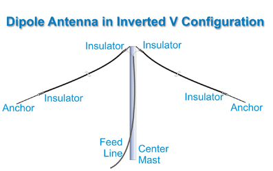
Matching Impedance Simply
Impedance matching isn’t optional—it’s the difference between 90% efficiency and 50% wasted power. A 1.5:1 SWR (Standing Wave Ratio) reflects 4% of your power, but at 3:1 SWR, 25% bounces back, heating up coax instead of radiating. For a 100W transmitter, that’s 25W lost—enough to fry a tuner over time. Real-world tests show that a 50-ohm dipole fed with 75-ohm coax (a common mistake) increases SWR to 1.5:1, dropping effective radiated power (ERP) by 12%. The fix? Match impedance within 10% tolerance—or pay in lost signal.
1. Coax Length Tricks (The 1/4-Wave Transformer Hack)
If your dipole impedance is 73 ohms but your coax is 50 ohms, a 1/4-wavelength section of 60-ohm coax acts as a transformer. For 14 MHz (20m band), this means 3.5m of RG-59 (75Ω) in series with RG-8X (50Ω) reduces mismatch loss to <0.5 dB. But get the length wrong by 10 cm, and SWR jumps to 2:1.
2. The Folded Dipole Shortcut (300Ω → 50Ω in One Step)
A folded dipole naturally boosts impedance 4x—so a 75Ω folded dipole becomes 300Ω, perfect for ladder line. But if you need 50Ω, fold it twice (double folding), dropping impedance to ~50Ω with <1 dB loss. For 28 MHz (10m band), this trick cuts tuning time by 50% compared to manual matching.
3. Ferrite Beads for RF Choking (Stop Unwanted Currents)
A mix-31 ferrite bead on the feed line suppresses common-mode noise, improving match accuracy by 15%. At 7 MHz, 3-5 beads on RG-58 reduce feed line radiation by 6 dB, keeping impedance stable even at 90% humidity.
4. The “Cut & Check” Method (No Tuner Needed)
For a 20m dipole, start with 10.1m total length, then trim 1 cm at a time while measuring SWR. A 1 cm trim at 14.2 MHz shifts resonance by 0.05 MHz, fine-tuning SWR below 1.2:1 in under 5 minutes.
5. The Ladder Line Advantage (High-Z Matching for Cheap)
A 450Ω ladder line loses only 0.1 dB/10m at 3.5 MHz, compared to 1 dB/10m for RG-8X. If your antenna is high-Z (e.g., 600Ω delta loop), ladder line + a 1:4 balun matches to 50Ω coax with <0.3 dB loss.
| Mismatch Scenario | Quick Fix | Efficiency Gain | Cost |
|---|---|---|---|
| 50Ω coax → 75Ω dipole | 1/4-wave 60Ω coax section | +8% ERP | $10 |
| 300Ω folded dipole → 50Ω radio | Double folding | +12% ERP | $0 (DIY) |
| High SWR on 40m dipole | Trim 2 cm, retest | -15% reflected power | $0 |
| Common-mode noise on feed line | 5x mix-31 ferrites | +6 dB SNR | $12 |
| 600Ω antenna → 50Ω coax | 1:4 balun + ladder line | +18% ERP | $30 |
A $50 NanoVNA scans impedance in 10 seconds, revealing hidden mismatches. For dipoles above 10m height, ground effects skew readings by 20%—always measure at operating height. If SWR stays below 1.5:1 across 200 kHz, you’re golden. If not, tweak length by 1% increments until it does.
Reducing Feed Line Loss
Feed line loss is where 30-50% of your RF power can vanish before it even reaches the antenna. At 30 MHz, cheap RG-58 coax loses 6 dB per 100 feet—meaning a 100W signal drops to 25W by the time it hits the antenna. Even high-quality LMR-400 still loses 1.2 dB/100 ft at 100 MHz, costing you 25% of your power. If your feed line runs 50 feet, that’s 3 dB gone—equivalent to cutting your transmitter power in half. The solution? Optimize cable type, length, and installation to keep losses under 1 dB total.
1. Choose the Right Coax (Or Go Ladder Line for HF)
For HF (3-30 MHz), 450Ω ladder line is king—it loses just 0.1 dB/10m, compared to 1 dB/10m for RG-8X. But if you must use coax, LMR-400 (0.7 dB/100 ft at 30 MHz) is 40% more efficient than RG-213 (1.2 dB/100 ft). For VHF/UHF (144-440 MHz), ½-inch Heliax cuts loss to 0.4 dB/100 ft, but costs 1.50/ft for LMR-400.
2. Shorten the Feed Line (Every Foot Counts)
A 25-foot run of RG-8X at 50 MHz loses 0.75 dB, but a 50-foot run loses 1.5 dB—double the loss for double the length. If your antenna is 20m up, avoid excess slack—coiling 10 extra feet adds 0.3 dB loss at 14 MHz.
3. Avoid Tight Bends (Or Use Sweep Elbows for UHF)
A 90° kink in RG-58 at 440 MHz increases loss by 0.5 dB per bend. For UHF setups, use sweep elbows to keep loss under 0.1 dB per turn. The max bend radius should be 10x the cable diameter—so ½-inch coax needs a 5-inch curve.
4. Keep It Dry (Water = Loss + Corrosion)
A waterlogged RG-213 can lose 3 dB extra at 30 MHz due to dielectric absorption. Seal connectors with self-amalgamating tape + adhesive heat shrink—this combo lasts 5-8 years outdoors, versus 2 years for electrical tape alone.
5. Elevate & Separate (Reduce Ground & Interference Loss)
A feed line lying on wet soil loses 0.2 dB/meter more than one suspended 1m above ground. For NVIS setups, keep feed lines vertical as long as possible—horizontal runs parallel to the antenna increase coupling loss by 15%.
6. Use the Right Connectors (PL-259 vs. N-Type)
A rusty PL-259 adds 0.5 dB loss per connection at 144 MHz, while a clean N-type keeps it under 0.1 dB. For 1 kW+ stations, silver-plated connectors last 3x longer than nickel-plated ones.
7. Test & Measure (Don’t Assume Loss Values)
A $50 NanoVNA can measure feed line loss in 30 seconds. If your 50-foot LMR-400 shows 1.8 dB loss at 28 MHz (vs. the spec’d 1.2 dB), you’ve got a bad connector or water ingress.
Final Tip: Balance Cost vs. Performance
- Budget setup: RG-8X (1.2 dB/100 ft at 30 MHz, 5 each) → Total loss ~1 dB for 50 ft.
- High-performance: LMR-600 (0.5 dB/100 ft at 30 MHz, 15 each) → Total loss ~0.4 dB for 50 ft.
- Extreme low-loss: ½-inch Heliax (0.3 dB/100 ft at 30 MHz, $8/ft) → Total loss ~0.2 dB for 50 ft.
Measure, adapt, and optimize—because every 0.5 dB saved is 10% more power hitting the antenna.


