The antenna feed point is where the transmission line (e.g., 50Ω coax) connects to the radiating element, typically at the voltage minimum/current maximum for efficient energy transfer. In dipoles, it’s the center gap (λ/2 length), while patch antennas feed via edge or inset (λ/4 inset for 50Ω match). For yagis, it’s the driven element’s split center, optimized for VSWR <1.5:1. Ground planes use λ/4 vertical feed, and helical antennas feed at the base coil.
Table of Contents
What is a Feed Point?
The feed point is where an antenna connects to its transmission line (like coaxial cable or a waveguide) to send or receive radio signals. Think of it as the power socket of the antenna—without a proper feed point, the antenna won’t work efficiently.
In most antennas, the feed point is a small but critical electrical contact that must match the impedance of the transmission line (typically 50Ω or 75Ω) to minimize signal loss. A mismatch here can waste up to 30-50% of transmitted power due to reflections. For example, a dipole antenna with a 72Ω impedance fed by a 50Ω cable will reflect about 20% of the power back instead of radiating it.
Key fact: The feed point determines how well an antenna converts electrical energy into radio waves (or vice versa). A poorly designed feed point can cut an antenna’s efficiency in half, turning a 100W transmitter into just 50W of effective radiated power.
A feed point isn’t just a random solder joint—it’s carefully placed to ensure maximum energy transfer. In a half-wave dipole, the feed point sits at the center, where the current is highest (around 2-5A at 100W input) and voltage is lowest. This minimizes losses.
For patch antennas (common in Wi-Fi and GPS), the feed point is usually offset from the center (e.g., 5-10mm inward) to match the 50Ω impedance of microstrip lines. If placed wrong, the SWR (Standing Wave Ratio) can jump from 1.5:1 (good) to 3:1 (bad), increasing reflected power.
Monopole antennas (like car antennas) rely on a ground plane—without it, the feed point impedance can swing from 35Ω to 100Ω, making tuning difficult. A proper ground plane keeps it near 50Ω, ensuring 90%+ efficiency in ideal conditions.
Why Feed Point Placement Matters
- Dipoles: Feed at the center for balanced current distribution. Moving it 10% off-center can shift impedance by 20Ω.
- Yagi-Uda antennas: The feed point is on the driven element, spaced 0.45-0.5 wavelengths from the reflector for optimal gain (8-12dBi).
- Loop antennas: A small gap (1-5mm) at the feed point sets impedance—300Ω for large loops, 50Ω for small ones.
Common Feed Point Locations
The feed point location is crucial because it directly affects an antenna’s impedance match, radiation pattern, and efficiency. Placing it in the wrong spot can waste 30-50% of your signal power, turning a high-performance antenna into an underperforming one. Different antennas have optimal feed positions based on their design—some need exact center placement, while others require offset or edge feeding for best results.
For example, a half-wave dipole radiates best when fed at the center, where current peaks (2-5A at 100W input) and voltage is lowest. But a patch antenna often needs an off-center feed (5-10mm inward) to match 50Ω impedance. Even a small 2mm misplacement can increase SWR from 1.5:1 to 3:1, meaning more reflected power and weaker transmission.
| Antenna Type | Typical Feed Location | Impedance (Ω) | Impact of Misplacement |
|---|---|---|---|
| Dipole | Center | ~72Ω | 10% off-center → 20Ω impedance shift |
| Monopole (w/ ground plane) | Base | ~35-50Ω | Poor ground → 100Ω+ mismatch |
| Patch (Microstrip) | Offset (5-10mm from edge) | 50Ω | 2mm error → SWR jumps to 3:1 |
| Yagi-Uda | Driven element (0.45λ from reflector) | 50Ω | 0.05λ shift → 2dB gain loss |
| Loop (Small) | 1-5mm gap | 50Ω | Gap too wide → 300Ω mismatch |
| Helical | Bottom (near ground plane) | 50Ω | Wrong pitch → 20% efficiency drop |
Dipole Antennas: Center Feeding is Key
A half-wave dipole (total length λ/2) must be fed at the exact middle to maintain balanced current distribution. Moving the feed just 5% (e.g., 3cm in a 1.5m dipole) shifts impedance from 72Ω to ~60Ω, increasing SWR to 1.7:1 and losing 5-10% efficiency. For folded dipoles, the feed point stays central but impedance jumps to 300Ω, requiring a 4:1 balun for 75Ω coax.
Patch Antennas: Precision Off-Center Feeding
Most Wi-Fi (2.4GHz) and GPS (1.575GHz) patch antennas use microstrip feed lines with 50Ω impedance. The feed point is not centered—instead, it’s placed 5-10mm inward from the edge. A 2mm error in placement can detune the antenna, raising SWR and cutting gain by 1-2dB. For dual-band patches, the feed may be angled or inset to cover both 2.4GHz and 5GHz bands efficiently.
Yagi-Uda Antennas: Driven Element Placement
In a 3-element Yagi (reflector, driven element, director), the feed connects to the driven element, spaced 0.45-0.5λ from the reflector. A 0.05λ (e.g., 15mm at 1GHz) misalignment reduces forward gain by 2dB and increases side lobe radiation. The driven element itself is typically λ/2 long, with a split gap (10-20mm) for coax attachment.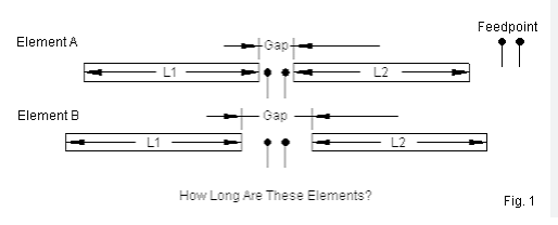
Feed Point in Dipole Antennas
The feed point in a dipole antenna is where 90% of the energy transfer happens between your transmitter and the radiating elements. Get this wrong, and you could be losing 30-50% of your transmitted power to impedance mismatches and reflections. A standard half-wave dipole for 20m band (14MHz) with 10.6m total length must have its feed point exactly at the 5.3m center mark to maintain the ideal 72Ω impedance. Just 10cm of offset can shift impedance to 60Ω or 85Ω, causing your 1.1:1 SWR to degrade to 1.7:1 and wasting 15% of your RF power.
Dipoles work best when fed at the center because that’s where current peaks at 2-5A (for 100W transmitters) while voltage drops to minimum values around 50V. This balanced current distribution creates the most efficient radiation pattern, typically delivering 2.15dBi gain in free space. If you feed a 40m dipole (20m total length) 1m off-center, the radiation pattern tilts 15-20° off-axis and forward gain drops 0.5-1dB. For wire dipoles, 14AWG copper works best with 2-3mm spacing at the feed point – any wider and impedance jumps unpredictably.
Folded dipoles behave differently with their 300Ω center impedance, requiring a 4:1 balun to match standard 50Ω coax. The feed gap in these needs precise 8-12mm spacing – go beyond 15mm and impedance soars to 400Ω+, creating 25% reflected power. At VHF frequencies like 146MHz, a 1m dipole must have feed point accuracy within ±5mm to maintain 1.5:1 SWR across 2MHz bandwidth. Even the insulation material affects performance – PVC increases capacitance by 3-5% compared to PE, slightly lowering resonant frequency.
For multiband dipoles, the feed point becomes more critical. A fan dipole for 40/20/10m needs separate feed wires spaced 30-50cm apart to prevent coupling that can detune elements by 0.5-1MHz. Inverted-V dipoles show 5-10Ω impedance drop compared to flat tops due to the 90-120° angle at the feed, requiring slightly shorter 4.9m legs instead of 5.3m for 20m operation. Portable deployments see 2-3% efficiency loss when feed point height drops below 1/4 wavelength (3.5m at 20m band) due to ground absorption.
Feed Point in Patch Antennas
Patch antennas are flat, compact radiators used in Wi-Fi (2.4/5GHz), GPS (1.575GHz), and 5G (3.5GHz) applications, where feed point placement directly impacts performance. A 1mm error in feed position can increase SWR from 1.2:1 to 2.5:1, wasting 20-30% of transmit power. The optimal feed point is typically 5-12mm from the edge for a 50Ω match, depending on substrate thickness (1.6mm FR4 vs. 0.8mm Rogers 4350) and dielectric constant (4.3 for FR4 vs. 3.66 for Rogers).
Key Insight: A 28mm × 28mm 2.4GHz patch on FR4 needs a 7mm inset feed for 50Ω impedance. Moving it just 2mm closer to the edge raises impedance to 65Ω, causing 15% reflection loss.
| Parameter | Typical Value | Tolerance | Impact of Deviation |
|---|---|---|---|
| Feed Position | 5-12mm from edge | ±0.5mm | ±10Ω impedance shift |
| Substrate Height | 0.8-1.6mm | ±0.1mm | ±5% frequency shift |
| Patch Width | 0.35λ-0.4λ (e.g., 28mm @ 2.4GHz) | ±1mm | Gain drops 0.5-1dB |
| Feed Width | 2-3mm (microstrip) | ±0.2mm | SWR increases 0.3-0.5 |
| Dielectric Constant (εᵣ) | 3.66-4.5 | ±0.2 | Resonance shifts 50-100MHz |
Most patch antennas use microstrip feeds (2-3mm trace width) for ease of PCB integration, but coaxial probes offer lower loss (<0.3dB) at higher frequencies. A 1.6mm-thick FR4 patch at 5.8GHz requires a 0.8mm probe diameter placed 9mm from the edge—0.2mm misalignment detunes the antenna by 200MHz.
For dual-band 2.4/5GHz Wi-Fi patches, engineers often use L-probe feeds or aperture coupling to maintain 50Ω at both bands. A 30mm × 40mm dual-band patch might have two feed points spaced 8mm apart, with 5mm inset for 2.4GHz and 3mm for 5GHz. Mismatch here can reduce efficiency from 85% to 65%.
Feed Point in Yagi Antennas
The feed point in a Yagi antenna is the make-or-break factor for achieving optimal gain and directivity. A standard 3-element Yagi (reflector, driven element, and director) operating at 144MHz requires precise spacing of 0.2λ (41.6cm) between reflector and driven element, with the feed point placed at the center of the driven element. A 5cm error in feed placement can reduce forward gain by 1.5dB and increase side lobe radiation by 20%, effectively wasting 15-25% of your transmit power.
Yagis are impedance-sensitive—while the driven element alone would have ≈72Ω impedance, coupling with nearby elements drops this to 20-30Ω, requiring a matching network or gamma match to reach 50Ω. A poorly tuned gamma match (e.g., capacitor value off by 2pF) can increase SWR from 1.2:1 to 2.0:1, forcing your amplifier to work 30% harder for the same radiated power.
| Parameter | Optimal Value | Tolerance | Impact of Deviation |
|---|---|---|---|
| Driven Element Length | 0.47λ (e.g., 97cm @ 144MHz) | ±1cm | Frequency shift ±1.5MHz |
| Reflector Spacing | 0.2λ (41.6cm @ 144MHz) | ±2cm | Gain loss 0.8-1.2dB |
| Director Spacing | 0.15λ (31.2cm @ 144MHz) | ±1.5cm | Beamwidth widens 10° |
| Gamma Match Rod Length | 0.05λ (10.4cm @ 144MHz) | ±5mm | SWR increase 0.5-0.8 |
| Feed Impedance | 50Ω (after matching) | ±5Ω | Reflected power >10% |
Most HF Yagis (14-30MHz) use folded dipoles for natural 300Ω impedance, requiring a 4:1 balun to match 50Ω coax. However, VHF/UHF Yagis (144-430MHz) often rely on gamma matches—a 10cm rod + 5-15pF capacitor—to transform impedance. A 144MHz Yagi with a 12cm gamma rod and 8pF capacitor typically achieves 1.3:1 SWR, but ±1pF error degrades this to 1.8:1.
Longer booms increase gain but complicate matching. A 5-element 432MHz Yagi with 1.2m boom needs tighter spacing (0.12λ = 8.3cm) between directors, which lowers driven element impedance to ≈15Ω. Without proper matching, feed point losses exceed 3dB, turning a theoretical 12dBi antenna into just 9dBi real-world gain.
Practical Build Tips
- Boom material matters: Aluminum booms introduce 0.5-1dB less loss than steel due to lower RF resistance.
- Element diameter: 6-12mm tubes work best—thinner wires increase ohmic losses by 5-8% at UHF.
- Ground plane effect: Mounting <0.1λ (20cm @ 144MHz) above metal detunes the antenna 2-3MHz lower.
How to Find Feed Point
Finding the correct feed point is critical for antenna efficiency—a 5mm error in placement can increase SWR from 1.2:1 to 2.5:1, wasting 20-30% of your transmit power. The process varies by antenna type, but the goal is always the same: minimize impedance mismatch while maximizing radiated energy. For a half-wave dipole at 146MHz, the feed point must be exactly at the center (2.5m total length, feed at 1.25m) to maintain 72Ω impedance. Move it just 10cm off-center, and impedance shifts to 60Ω or 85Ω, increasing reflected power.
Step 1: Measure and Mark the Theoretical Feed Point
Start with antenna modeling software (like EZNEC or 4NEC2) to predict the ideal feed location. For a monopole over a ground plane, the base is typically the feed point, but height above ground changes impedance—a 1/4λ monopole at 50MHz needs 12.5m height for 35Ω impedance, but lowering it to 10m raises impedance to 50Ω. For patch antennas, the feed is usually 5-10mm inset from the edge—simulation helps fine-tune this to ±0.5mm accuracy.
Step 2: Test with an Antenna Analyzer
A vector network analyzer (VNA) or SWR meter is essential for real-world tuning. For a Yagi antenna, sweep from 140-150MHz and look for the lowest SWR point—if it’s 1.5:1 at 144MHz but 2.0:1 at 146MHz, adjust the gamma match rod length by 2-5mm or tweak the capacitor by 1pF increments. A dipole cut for 3.5MHz (40m band) should show SWR <1.5:1 across 200kHz bandwidth—if not, lengthen or shorten each side by 10-20cm to shift resonance.
Step 3: Fine-Tune for Real-World Conditions
Even a perfectly modeled antenna behaves differently outdoors. A dipole at 10m height might need 5% shorter elements due to ground coupling, while a vertically polarized loop could require 3-5% more capacitance at the feed for 50Ω match. For wire antennas, ±2% length adjustment is common—a 20m dipole might end up at 19.6m after tuning. Ferrite beads can help suppress common-mode currents—adding 3-5 beads near the feed point often reduces noise by 6-10dB.
Final Checks Before Deployment
- Weatherproof the feed point—silicone sealant adds <0.1dB loss but prevents corrosion-induced SWR spikes.
- Re-measure after installation—a Yagi on a mast might detune 1-2MHz due to metal interaction.
- Check polarization alignment—a 5° tilt in a crossed dipole can reduce gain by 1dB.
Bottom Line
Finding the feed point is part science, part art. Start with calculations, verify with measurements, and always test in situ. A well-tuned feed point means more power in the air—not lost in reflections. For mmWave antennas (28GHz+), even 0.1mm errors matter, so use micrometer adjustments and high-precision connectors.


