The highest gain antennas are typically parabolic reflector dishes, achieving 30–50 dBi in C/Ku-band (4–18 GHz). Larger diameters (3–10 meters) enhance gain, with efficiency around 50–70%. For extreme gain (60+ dBi), horn-reflector antennas or cassegrain feeds are used in deep-space communication. Precise alignment (0.1° accuracy) and low-noise amplifiers (LNA) maximize performance. Smaller alternatives like Yagi-Uda antennas offer 10–20 dBi for UHF/VHF.
Table of Contents
What is Antenna Gain?
Antenna gain measures how well an antenna focuses radio frequency (RF) energy in a specific direction compared to an ideal isotropic antenna (which radiates equally in all directions). It’s expressed in decibels (dBi) for isotropic reference or dBd relative to a dipole antenna (1 dBd ≈ 2.15 dBi). For example, a 10 dBi gain antenna transmits 10x more power in its strongest direction than an isotropic antenna.
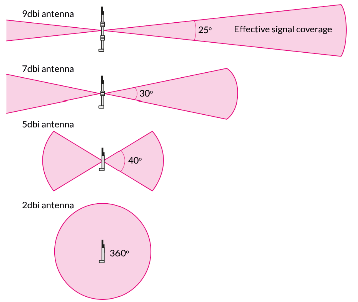
Gain depends on antenna design, size, and frequency. A small 2.4 GHz Wi-Fi dipole might have 2.15 dBi gain, while a large parabolic dish at the same frequency can exceed 24 dBi. Higher gain means longer range but narrower beamwidth—a trade-off between coverage area and signal strength. For instance, a 15 dBi Yagi antenna might have a 30° beamwidth, while a 5 dBi omni antenna covers 360° horizontally but with weaker signal reach.
Key Factors Affecting Antenna Gain
- Physical Size & Aperture – Larger antennas capture more RF energy. A 1-meter parabolic dish at 5.8 GHz can achieve 30 dBi gain, while a 0.3-meter dish at the same frequency maxes out at 22 dBi.
- Frequency & Wavelength – Higher frequencies allow tighter beam focus. A 2.4 GHz antenna needs twice the size of a 5.8 GHz antenna for similar gain.
- Efficiency Losses – Real-world antennas lose 10-20% efficiency due to cable resistance, impedance mismatch, and environmental factors. A theoretical 10 dBi antenna might deliver only 8.5 dBi in practice.
Gain vs. Real-World Performance
| Antenna Type | Typical Gain (dBi) | Beamwidth | Max Range (LOS, 100mW) |
|---|---|---|---|
| Omnidirectional | 2-5 dBi | 360° | ~300m |
| Dipole | 2.15 dBi | 75° (vertical) | ~200m |
| Yagi | 7-15 dBi | 30-60° | ~1-3 km |
| Parabolic Dish | 20-30 dBi | 5-15° | ~5-10 km |
Higher gain doesn’t always mean better performance. A 24 dBi dish is useless for indoor Wi-Fi because its 5° beamwidth requires precise alignment. Meanwhile, a 5 dBi omni antenna covers an entire office floor but struggles beyond 100 meters outdoors.
How Gain Impacts Signal Strength
Every 3 dB increase doubles power density in the main lobe. If a 3 dBi antenna transmits 100 mW, a 6 dBi antenna effectively delivers 200 mW in its focused direction. However, free space path loss (FSPL) reduces signal over distance. At 2.4 GHz, FSPL is ~80 dB at 100m, meaning even a 10 dBi antenna loses 70 dB of signal strength at that range.
How Antennas Work
Antennas convert electrical signals into radio waves (RF) and vice versa, acting as the bridge between electronics and free space. A simple quarter-wave monopole at 433 MHz is just 17.3 cm long—precisely matched to the wavelength. When fed with 5W of power, it radiates ~3 dBi gain omnidirectionally, covering ~1 km line-of-sight in ideal conditions. But how does this energy actually travel?
The radiation efficiency of an antenna depends on its impedance match to the transmitter. A 50-ohm antenna fed by a 50-ohm coaxial cable might lose only 0.5 dB of power, but a 75-ohm mismatch can waste over 20% of the energy as heat. Real-world antennas rarely exceed 90% efficiency due to conductor losses, dielectric absorption, and environmental interference.
Dipole antennas, the most basic type, split a half-wavelength conductor into two ¼-wave arms. At 144 MHz (2-meter band), each arm measures 50 cm, creating a doughnut-shaped radiation pattern with 2.15 dBi gain. If you bend the arms downward at 45°, the gain drops to ~1 dBi but improves vertical coverage—a trick used in FM broadcast antennas.
Directional antennas like Yagis and dishes focus energy by canceling waves in unwanted directions. A 5-element Yagi at 900 MHz has 10 dBi gain because its parasitic elements reflect and direct energy forward, narrowing the beamwidth to 60°. But this comes at a cost: the front-to-back ratio (how much power leaks backward) might be 15 dB, meaning 3% of the energy still radiates in the wrong direction.
Critical detail: Antennas don’t “amplify” signals—they reshape radiation patterns. A 20 dBi dish doesn’t magically boost a 1W transmitter to 100W; it just squeezes the same power into a 5° cone, increasing signal strength in that direction by 100x compared to an isotropic radiator.
Frequency dictates antenna size. A ¼-wave CB antenna at 27 MHz is 2.7 meters tall, while a 5G mmWave antenna at 28 GHz fits 8.5 mm elements on a smartphone PCB. Smaller antennas have lower efficiency—a mmWave array might lose 40% of its power to impedance mismatches and PCB losses.
Ground planes drastically alter performance. A ¼-wave whip on a car roof acts like a ½-wave dipole because the metal body acts as a mirror, doubling the effective length. Without a ground plane, the same antenna’s gain drops by 3 dB, cutting its range in half.
Polarization matters. A vertically polarized antenna loses 20 dB (99% power) when receiving horizontal polarization—why Wi-Fi routers use dual-polarized MIMO antennas to combat multipath interference.
Key Differences Explained
When choosing an antenna, gain, frequency, and radiation pattern are the three most critical factors—but they interact in ways that aren’t always obvious. A high-gain Yagi might seem like the best choice for long-range Wi-Fi, but if it’s optimized for 5.8 GHz, it’ll perform poorly at 2.4 GHz due to wavelength mismatch. Here’s how these variables actually play out in real-world scenarios.
Gain vs. Coverage Trade-Off
| Antenna Type | Gain (dBi) | Beamwidth | Best Use Case |
|---|---|---|---|
| Omnidirectional | 2–5 dBi | 360° | Indoor Wi-Fi, IoT sensors |
| Dipole | 2.15 dBi | 75° (vertical) | FM radio, handheld transceivers |
| Yagi | 7–15 dBi | 30–60° | Point-to-point links, rural Wi-Fi |
| Parabolic Dish | 20–30 dBi | 5–15° | Satellite, long-distance backhaul |
A 5 dBi omni antenna spreads its signal evenly, making it ideal for covering a 100-meter radius in an office. But if you need to reach 1 km, a 15 dBi Yagi focuses energy into a 40° cone, sacrificing wide-area coverage for distance. The catch? If the Yagi is even 10° off-axis, signal strength drops by 3 dB—cutting effective power in half.
Frequency Determines Physical Size
- A 900 MHz antenna needs elements ~16.7 cm long (¼ wavelength).
- The same antenna scaled to 2.4 GHz shrinks to 3.1 cm.
- At 28 GHz (5G mmWave), elements are just 2.7 mm—but atmospheric absorption loses 0.5 dB per meter.
This is why low-frequency antennas (e.g., 400 MHz for LoRa) penetrate buildings better but require larger installations, while high-frequency antennas (e.g., 60 GHz WiGig) offer multi-gigabit speeds but struggle beyond 50 meters.
Efficiency Losses Add Up
Even a well-designed antenna suffers real-world losses:
- Coaxial cable resistance: 3 dB loss per 100 ft at 2.4 GHz (RG-58 cable).
- Impedance mismatch: Up to 20% power loss if SWR exceeds 1.5:1.
- Environmental interference: Rain attenuates 5.8 GHz signals by 0.01 dB/km, while foliage can add 10 dB loss.
Common Uses Compared
Antennas aren’t one-size-fits-all—frequency, gain, and form factor dictate where they excel. A 2.4 GHz omnidirectional antenna with 5 dBi gain might blanket a 3,000 sq ft office with Wi-Fi, but that same antenna would fail miserably for a 10 km point-to-point link, where a 24 dBi parabolic dish becomes essential. Here’s how different antennas fit into real-world applications.
Wi-Fi Routers typically use dual-band dipole arrays (2.4 GHz and 5 GHz) with 3–6 dBi gain per element. The low gain ensures 360° coverage, but range is limited to ~100 meters outdoors. In a crowded apartment building, signal strength can drop by 20 dB due to walls and interference, which is why mesh networks with multiple low-gain nodes often outperform a single high-gain antenna.
Cellular boosters rely on 7–10 dBi Yagi antennas for outdoor reception, paired with 2–3 dBi dome antennas indoors. A 4G LTE signal at 700 MHz penetrates buildings better than 3.5 GHz 5G, but the lower frequency requires a larger antenna (50 cm vs. 15 cm). In rural areas, a 12 dBi panel antenna can pull in a -110 dBm signal from a tower 10 km away, while urban environments need smaller, wider-coverage antennas to handle multipath reflections.
Satellite dishes demand extreme precision—a 60 cm Ku-band dish for 12 GHz signals must be aligned within 0.5° to maintain a stable link. Rain fade at this frequency can cause 10 dB signal loss during a storm, equivalent to 90% power drop. Compare that to Starlink’s phased array, which uses 1,600 tiny antennas to dynamically steer beams without moving parts, but sacrifices peak gain (29 dBi vs. 35 dBi for a traditional dish) for flexibility.
RFID and IoT devices often use 2 dBi loop or patch antennas because their 1–10 meter range doesn’t need high gain. A UHF RFID tag at 915 MHz might have 0.5 dBi gain, just enough to backscatter a signal 3 meters to a reader. For long-range LoRa (868 MHz), a 6 dBi fiberglass whip can stretch coverage to 15 km in open terrain, but only 500 meters in a dense city.
Military and aviation antennas prioritize reliability over efficiency. A HF blade antenna on a fighter jet might tolerate -40°C to +70°C and 500 mph winds, but its 3 dBi gain is worse than a civilian equivalent. Meanwhile, a GPS antenna needs 5 dB of front-end amplification to overcome 1575 MHz signal losses from atmospheric distortion.
Signal Quality Factors
Signal quality isn’t just about raw power—it’s a mix of strength, stability, and clarity that determines whether your wireless link works reliably or fails unpredictably. A -70 dBm Wi-Fi signal with 20 dB noise floor performs worse than a -85 dBm signal with 5 dB noise, because the signal-to-noise ratio (SNR) dictates real-world throughput. In 4G LTE networks, just 3 dB of additional interference can slash data rates by 50%, turning a 30 Mbps connection into a 15 Mbps crawl.
| Factor | Typical Impact | Acceptable Range | Measurement Method |
|---|---|---|---|
| RSSI (Received Signal Strength) | -30 dBm (excellent) to -90 dBm (poor) | -50 dBm to -70 dBm for most apps | Spectrum analyzer, Wi-Fi scanner |
| SNR (Signal-to-Noise Ratio) | <10 dB = unusable, >25 dB = optimal | 15–25 dB for HD video | Calculated (RSSI – Noise Floor) |
| Delay Spread (Multipath) | >500 ns causes symbol interference | <100 ns for 5G NR | Channel impulse response |
| Phase Noise | Degrades QAM-256 above -100 dBc/Hz | <-110 dBc/Hz @ 1 GHz | Phase noise analyzer |
| Polarization Mismatch | Up to 20 dB loss if cross-polarized | <3 dB loss preferred | Antenna alignment test |
Multipath fading is one of the biggest killers of signal integrity. In urban environments, 5 GHz signals bounce off buildings, creating nulls up to 30 dB deep every half-wavelength (3 cm at 5 GHz). MIMO systems combat this by using 4×4 antenna arrays to exploit multipath, boosting throughput by 2–3x compared to SISO. But if antennas are spaced less than ½ wavelength apart, correlation reduces diversity gain—a 10 cm gap works for 2.4 GHz, but needs 2.5 cm at 5.8 GHz.
Phase noise wrecks high-order modulation. A 5G mmWave carrier at 28 GHz with -90 dBc/Hz phase noise at 1 MHz offset will struggle with 256-QAM, limiting peak rates to 1 Gbps instead of the theoretical 3 Gbps. Cheap oscillators in consumer routers often have 10–20 dB worse phase noise than enterprise gear, explaining why two ”5-bar signal” connections can deliver wildly different speeds.
Polarization loss is frequently overlooked. A circularly polarized drone antenna loses 3 dB when talking to a linear polarized ground station—equivalent to halving transmit power. This is why dual-polarized LTE base stations use ±45° slant polarization to maintain <1 dB loss regardless of device orientation.
Atmospheric absorption varies wildly by frequency. While 2.4 GHz waves lose 0.01 dB/km in clear air, 60 GHz oxygen absorption eats 15 dB/km, restricting WiGig to room-scale use. Rain boosts 18 GHz satellite link losses from 0.05 dB/km to 0.5 dB/km—enough to trigger modem fallback from 16APSK to QPSK, cutting bandwidth by 60%.
Choosing the Right One
Picking the perfect antenna isn’t about chasing the highest specs—it’s about matching physics to your actual needs. A 30 dBi parabolic dish might seem impressive, but if you’re covering a 500 sq ft apartment, a $20 omnidirectional antenna with 5 dBi gain will perform better. The right choice balances frequency, environment, and use case—not just raw numbers.
Start with operating frequency, because it dictates everything from antenna size to real-world range. A 900 MHz LoRa antenna needs elements 16 cm long, giving it 3–5 dB better building penetration than 2.4 GHz Wi-Fi, but at the cost of 50% lower data rates. If you’re deploying smart meters in a city, the 868 MHz band might reach 3 km through concrete, while 2.4 GHz struggles past 500 meters. But if you need high-speed video, 5.8 GHz delivers 400 Mbps—if you can accept 10x worse obstacle penetration.
Gain requirements depend on whether you need coverage or distance. A 2 dBi rubber duck antenna works fine for a handheld radio communicating 1–2 km in open terrain, but a 15 dBi Yagi becomes essential for 10 km point-to-point links. However, high-gain antennas demand precision alignment—a 20 dBi dish with a 10° beamwidth loses 50% signal strength if it’s just 5° off-target. For mobile applications like drones or vehicles, a low-gain omnidirectional antenna (even with 3 dB lower output) often outperforms a misaligned high-gain directional one.
Environmental factors play a huge role. In humid coastal areas, 5.8 GHz signals suffer 0.02 dB/km extra loss from water vapor absorption, while metal-rich urban environments create multipath interference that can slash Wi-Fi throughput by 70%. If you’re mounting outdoors, UV-resistant radomes add 5–10 years to antenna lifespan, while corroded connectors can introduce 3 dB insertion loss—halving your effective power.
Budget constraints force trade-offs. A $100 log-periodic antenna covers 200 MHz–6 GHz for spectrum monitoring, but a $300 tuned Yagi delivers 3 dB better gain at specific frequencies. For IoT deployments, a $15 PCB trace antenna might suffice for 10-meter ranges, while industrial applications often need $200 ruggedized antennas that survive -40°C to +85°C with IP67 waterproofing.


