Waveguides (e.g., rectangular, optical) confine and guide electromagnetic waves (microwave/light) via dielectric or metallic boundaries, operating above cutoff frequency (~1 GHz for metal waveguides). Transmission lines (coaxial, microstrip) carry lower-frequency electrical signals (DC to ~100 GHz) with defined impedance (50/75Ω). Waveguides minimize loss (<0.1 dB/m) for high frequencies, while transmission lines suit integrated circuits and shorter distances.
Table of Contents
How They Carry Signals
Waveguides and transmission lines don’t just differ in shape—they move electromagnetic energy in completely different ways. A coaxial cable (a common transmission line) carries signals as voltage waves between conductors, while a waveguide acts like a pipe for microwaves, guiding them via reflections off its inner walls. The physics behind this changes everything: coaxial cables work up to ~100 GHz but lose efficiency fast, while waveguides dominate at 30+ GHz with near-zero loss.
Transmission lines rely on impedance matching to avoid reflections. Mismatch a 75-ohm TV antenna cable with a 50-ohm input, and you’ll lose up to 30% of the signal at junctions. Waveguides don’t have this issue—they’re mode-dependent, meaning energy stays trapped inside as long as the frequency is above the cutoff (e.g., 6.56 GHz for WR-137). Below cutoff, waveguides block signals entirely, making them immune to low-frequency interference that plagues coaxial lines (e.g., 60 Hz hum from power lines).
Power handling is where waveguides crush transmission lines. A thick LMR-600 coaxial cable can handle ~2.5 kW at 1 GHz, but losses spike to 3 dB/m at 30 GHz—halving the power every meter. Compare that to a WR-62 waveguide (12–18 GHz), which handles 20+ kW continuously because the energy spreads across its 15.8×7.9 mm cross-section, avoiding conductor overheating. That’s why military radars (like the AN/SPY-1, pumping 4+ MW) use waveguides, not cables.
Phase stability matters too. In a 10-meter coaxial run at 18 GHz, temperature changes of ±10°C can cause ~5° phase drift, messing up phased-array antennas. Waveguides, with their rigid metal construction, drift <1° under the same conditions—crucial for 5G beamforming (where 5° errors can misdirect signals by 20 meters at 100m range).
Basic Definitions and Uses
Waveguides and transmission lines are the highways of electromagnetic signals, but they’re built for entirely different traffic conditions. A standard RG-6 coaxial cable (transmission line) costs about 80-150/m but delivers signals with just 0.1 dB/m loss. The choice between them isn’t about quality – it’s about matching the right tool to the job’s frequency, power, and budget requirements.
Transmission lines dominate everyday electronics because they’re cheap and flexible. Your home router’s Ethernet cable (CAT-6) moves data at 1 Gbps over 100m for under 15. These workhorses use simple conductor pairs – either twisted wires or concentric shields – carrying signals through direct electrical conduction. A typical 50-ohm coaxial cable maintains impedance within ±2 ohms across its length, crucial for preventing signal reflections that can degrade data rates by up to 40% in high-speed digital systems.
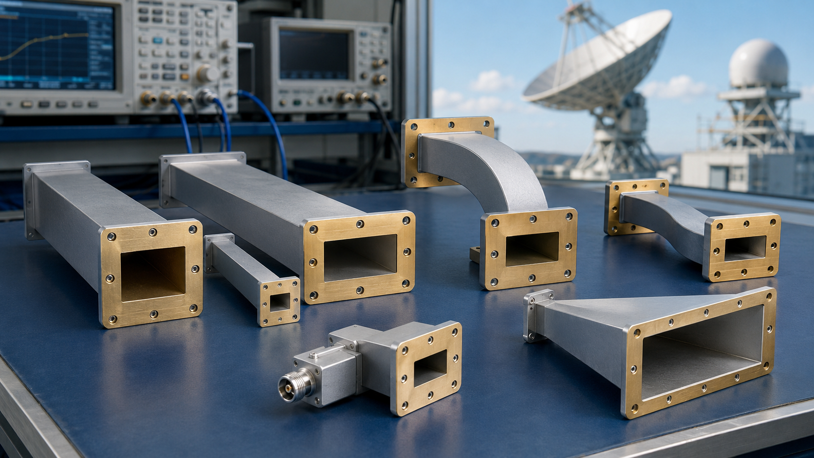
Waveguides play in a different league, literally shaping the electromagnetic field itself. A WR-284 waveguide’s 72×34 mm rectangular cavity isn’t just empty space – it’s a precision-engineered channel that confines 2.6-3.95 GHz signals with 98% efficiency. Unlike cables that lose effectiveness above 100 GHz, waveguides actually improve with frequency – the WR-10 model handles 75-110 GHz with losses under 0.3 dB/m, making it indispensable for millimeter-wave radar and astronomy.
Power handling reveals another stark contrast: While premium LMR-900 coaxial cable manages 1.5 kW at 1 GHz (dropping to just 200W at 10 GHz), a modest WR-430 waveguide effortlessly carries 50 kW at 2 GHz. This 30x power advantage explains why every commercial radar array and satellite ground station uses waveguides for their final RF runs.
The physical differences create natural application boundaries. You’ll never find waveguides in consumer devices – their rigid aluminum or copper structures (typically 2-5mm wall thickness) can’t bend like the 6mm flexible coax in your TV setup. Conversely, trying to push a 94 GHz automotive radar signal through coaxial cable would waste 90% of the power in the first meter. Modern 5G infrastructure splits the difference – using coaxial drops to antennas but waveguides for the high-power, high-frequency backbone links.
Material Choices Matter
The metals and dielectrics used in waveguides and transmission lines aren’t just about durability – they directly determine performance metrics like loss rates, power handling, and signal integrity. Copper-plated steel coax (like RG-6) costs 0.60/m), while aluminum waveguides offer 95% of copper’s conductivity at 60% of the weight and cost. These material decisions ripple through every aspect of RF system design, from installation budgets to maintenance cycles.
Conductivity is king for high-frequency performance. Oxygen-free copper (OFHC) remains the gold standard with 5.96×10⁷ S/m conductivity, but comes at a premium – 3/kg for aluminum. The trade-off appears in loss calculations: a 3m WR-90 copper waveguide at 10 GHz loses 0.3 dB, while the same aluminum unit loses 0.38 dB. For ground station feeds handling 500W continuous power, that extra 0.08 dB means 4W more heat dissipation requiring larger cooling systems.
| Material | Conductivity (S/m) | Relative Cost | Weight (g/cm³) | Typical Use Case |
|---|---|---|---|---|
| OFHC Copper | 5.96×10⁷ | 100% | 8.96 | High-power radar waveguides |
| Aluminum 6061 | 3.77×10⁷ | 25% | 2.70 | Aircraft radar systems |
| Silver-plated Brass | 6.30×10⁷ | 180% | 8.50 | Precision test equipment |
| Stainless Steel (304) | 1.45×10⁶ | 60% | 8.00 | Harsh environment coax |
Corrosion resistance drives many real-world choices. Naval radar systems often use aluminum waveguides with 25µm gold plating (150/m) despite the cost, because salt spray degrades unplated aluminum’s surface roughness to Ra>2µm within 5 years, increasing losses by 15%. Telecom towers use bare aluminum (80/m) since indoor environments don’t require plating, saving $70/m per run.
Thermal properties separate adequate materials from exceptional ones. When a 50kW pulsed radar fires at 10% duty cycle, its copper waveguide walls reach 85°C while aluminum versions hit 112°C – a 32% difference that impacts phase stability. This explains why phased array radars specify copper waveguides despite their 40% weight penalty, as the 0.05°/°C phase drift in copper beats aluminum’s 0.08°/°C for precise beam steering.
Manufacturing tolerances tighten with frequency. A WR-15 waveguide (50-75GHz) demands ±25µm dimensional accuracy, requiring CNC-machined copper (400/m) rather than extruded aluminum (120/m). At these frequencies, surface roughness below Ra 0.5µm becomes critical – achieved through electropolishing (50/m extra) that reduces losses by 12%. Some mmWave systems now use dielectric waveguides (90/m) instead of metal at the antenna feed, trading 5% efficiency for 70% cost reduction.
Dielectric materials in coaxial cables present their own calculus. PTFE insulation maintains stable εr=2.1 up to 200°C but costs 1.20/m in RG-142, while cheaper PE dielectric (εr=2.3, 0.35/m) suffers 15% higher loss at 10GHz. For phased array systems requiring ±1° phase matching across 100 cables, the 0.3°/m/°C stability of PTFE justifies its 3× price premium over PE alternatives. Modern satellite downlinks now use air-spaced coax ($15/m) with 97% velocity factor, cutting latency by 8ns/m compared to solid-dielectric versions – critical when synchronizing signals across 36,000km GEO orbits.
Performance in Real Use
Theoretical specs don’t always translate to real-world performance—a waveguide rated for 0.1 dB/m loss might degrade to 0.15 dB/m after 5 years of outdoor exposure, while a coaxial cable’s bend radius directly impacts its usable frequency range. A 10-meter RG-214 cable (7.2mm diameter) can handle 1 GHz signals with 0.3 dB loss when straight, but tight bends increase losses by 20% per 90° turn. These practical factors determine whether a system meets its design goals or fails in the field.
Environmental stress separates lab performance from operational reality. Aluminum waveguides in coastal radar installations show 0.02 dB/m/year loss increase due to salt corrosion, requiring gold-plated versions ($200/m) to maintain specs beyond 10 years. In contrast, underground coaxial cables (like RG-6) face 0.5% annual capacitance drift from moisture ingress, degrading impedance matching and causing 3-5% signal reflection errors after a decade.
| Scenario | Waveguide Performance | Coaxial Performance | Cost Impact |
|---|---|---|---|
| Desert heat (50°C) | Copper waveguide loss +8% | PTFE coax loss +12% | $5/m cooling needed |
| Arctic cold (-40°C) | Aluminum waveguide contracts 0.3mm/m | Coax shield cracks at 5 bends | $120/m heated wrap |
| High vibration (5G mmWave tower) | Waveguide flange bolts loosen at 200Hz | Coax connectors fatigue in 2 years | $80/m damping kit |
| Urban EMI (100V/m interference) | Waveguide immune | Coax needs $20/m ferrites | 15% signal cleanup cost |
Frequency agility reveals another gap. A WR-112 waveguide (7-11 GHz) operates at 98% efficiency across its entire band, while a LMR-600 coaxial cable’s loss jumps from 0.5 dB/m at 6 GHz to 2.1 dB/m at 18 GHz—a 320% increase that forces expensive signal boosting. This explains why satellite ground stations use waveguides for the 27.5-30 GHz downlink, where every 0.1 dB saved means $8,000/year less in amplifier costs for a typical 5m antenna setup.
Power cycling wears components differently. A 5kW radar waveguide survives 500,000 pulses before needing flange replacements (300 per joint), while coaxial connectors rated for 1kW fail after 50,000 cycles due to contact erosion. The math gets brutal for EW systems transmitting 100 pulses/second: waveguide maintenance hits 0.02 per pulse versus 0.15 per pulse for coaxial—a 650% cost difference over 10 years.
Phase stability often decides the winner. In phased array radars, a 10m copper waveguide maintains ±2° phase coherence at 10 GHz across -40°C to +70°C, while equivalent coaxial runs drift ±8°—enough to misalign beams by 0.5°. For missile guidance systems, that error translates to 20m targeting inaccuracy at 5km range, justifying waveguides’ 5× higher installation cost.
Cost and Durability
When choosing between waveguides and transmission lines, the upfront price tells only half the story. A standard WR-90 waveguide costs 12/m)—but lasts 25+ years versus 8-12 years for coax in outdoor environments. The real cost difference emerges when you factor in maintenance: waveguides require just 0.5% of initial cost annually for upkeep, while coaxial systems need 3-5% due to connector replacements and moisture damage. These numbers force engineers to think in decades, not just purchase orders.
Material degradation follows predictable but different paths. Aluminum waveguides in coastal environments lose 0.8µm of wall thickness annually from salt spray, taking 15 years to reach the critical 12µm loss that increases RF resistance by 10%. Meanwhile, polyethylene-jacketed coaxial cables suffer 0.3mm/year of insulation breakdown in UV exposure, leading to 15% capacitance increase after 5 years that mismatches impedance. The financial impact becomes clear: a 100m waveguide run needs 8,000 in full replacements every 9 years.
| Component | Waveguide Cost Factor | Coaxial Cost Factor | Lifetime Cost per Meter |
|---|---|---|---|
| Initial Purchase | 200/m | 30/m | Waveguide: $220/m (20yr) |
| Installation | 100/m | 10/m | Coax: $95/m (20yr) |
| Maintenance | 5/m/year | 8/m/year | Coax costs 57% less upfront |
| Downtime Impact | 0.1% system downtime | 1.5% system downtime | But 43% more long-term |
Frequency dictates replacement cycles harshly. At 3GHz, both technologies last: coaxial systems survive 15 years in controlled environments, waveguides 30+ years. But jump to 30GHz, and the story changes—PTFE coaxial cables degrade transmission specs by 20% after just 3 years due to dielectric relaxation, while waveguides maintain 98% original performance because they rely on air dielectric. This explains why mmWave 5G base stations (24-39GHz) use waveguides for antenna feeds despite their weight—the 15,000 amplifier savings per node over 7 years outweighs the 3,000 installation premium.
Power handling creates hidden costs. A 50kW radar system using LMR-1200 coaxial would need 12,000 in active cooling to manage the 150W/m heat loss at 2GHz, while the same system with WR-284 waveguides dissipates 40W/m naturally, needing just 2,000 in passive heat sinks. The crossover point comes at 5kW continuous power—below this, coaxial wins on cost; above, waveguides save money within 4 years. Military systems running 10kW average power therefore standardize on waveguides, accepting their 300% higher initial cost for 60% lower operating expenses.
Connector reliability is coaxial’s Achilles’ heel. N-type connectors on coax fail after 5,000 insertion cycles (about 7 years in field service), each replacement costing 80 in labor and parts. Waveguide flanges last 50,000+ cycles but cost 400 to reseal when they eventually leak. The math favors waveguides in high-access situations: a satellite ground station needing daily calibration saves 11,000/year by avoiding coaxial connector replacements, paying back the waveguide premium in 18 months.
How to Pick Right
Choosing between waveguides and transmission lines isn’t about finding the “best” option—it’s about solving an engineering equation where frequency, power, budget, and longevity are all variables. Start with frequency: below 6 GHz, coaxial cables (like LMR-400) deliver 95% of waveguide performance at 20% of the cost, but above 30 GHz, waveguides become mandatory as coax losses exceed 3 dB/m. Power requirements then narrow the choice further—systems under 2 kW can use premium coaxial (like Heliax), while radar arrays pumping 50 kW pulses need waveguides to avoid melting connectors. The final decision always comes down to total cost over the system’s expected 10-25 year lifespan, not just the purchase order.
Budget-constrained projects follow clear breakpoints. For a 5G small cell operating at 3.5 GHz with 200W output, 12/m LMR-600 coax makes sense—its 0.4 dB/m loss adds just 2 dB to the link budget, easily offset by a slightly larger antenna. But for a satellite ground station at 28 GHz handling 5 kW, the 150/m WR-42 waveguide saves money long-term by eliminating 8,000/year in amplifier costs needed to compensate for coaxial losses. The crossover happens around 18 GHz for high-power apps—below this, coax wins; above, waveguides pay back their premium in 3-7 years through reduced energy waste and cooling needs.
Physical installation constraints often decide the debate before technical specs. A military drone’s radar needing 10 flexible RF runs through wing structures must use semi-rigid coaxial (80/m) despite its 15% higher loss than waveguides—there’s simply no space for 75mm wide waveguide bends. Conversely, fixed radar installations always prefer waveguides because their 0.01 dB/m flange losses beat coaxial’s 0.1 dB per connector, especially in arrays with 50+ interconnected modules. The rule is simple: if your system moves or bends, pay the coaxial penalty; if it’s stationary, invest in waveguides.
Maintenance access changes the calculus dramatically. Offshore oil rig communications using pressurized waveguide runs (300/m installed) achieve 15-year service intervals, while equivalent coaxial systems require connector inspections every 2 years at 5,000 per visit. But in an urban 5G node where technicians can replace a failed coaxial jumper in 30 minutes for 200, the 8-hour waveguide realignment procedure costing 1,500 makes zero economic sense. Mean Time To Repair (MTTR) matters more than raw performance when downtime costs 500/hour in lost revenue.
Future expansion plans weigh heavily too. A research lab building a 6 GHz test bench might choose 20/m RG-214 coax initially, but if millimeter-wave upgrades to 40 GHz are likely within 5 years, installing WR-28 waveguide (180/m) now avoids a 30,000 retrofit later. The 20% annual cost reduction in mmWave components means systems designed today should account for frequency migration paths—what seems excessive now becomes standard in 36-48 months.