A directional coupler’s “directional” property refers to its ability to separate forward and reflected signals (20-40dB isolation). It samples -10dB to -30dB of the main signal while introducing <0.5dB insertion loss. The coupler uses λ/4 waveguide spacing and 50Ω/75Ω impedance matching to achieve 90% power transfer efficiency, operating from DC-40GHz. Directionality ensures accurate VSWR measurements (1.05:1 precision) by isolating incident/reflected waves. Ferrite cores enhance frequency stability up to 18GHz.
Table of Contents
What a Directional Coupler Does
A directional coupler is a passive RF component that splits a small portion of a signal (typically 1% to 50%) from the main transmission line without significantly disrupting the original signal flow. For example, in a 50-ohm system, a 20 dB coupler will divert 10% of the input power (1 mW out of 10 mW) to the coupled port while letting 90% (9 mW) pass through to the output. The key advantage is minimal insertion loss (often 0.1 dB to 0.5 dB), meaning the main signal stays strong—critical in 5G base stations, radar systems, and cable TV networks where even a 1 dB loss can degrade performance by 20%.
Directional couplers work based on electromagnetic coupling between two transmission lines, usually microstrip or stripline, spaced precisely (e.g., 0.2 mm to 2 mm gap) to achieve desired coupling factors. A 10 dB coupler might use a quarter-wavelength (λ/4) section at 2 GHz (37.5 mm in FR4 PCB), while a 30 dB coupler requires tighter spacing (<0.1 mm) for weaker coupling. Frequency range is another critical factor—cheaper couplers cover 800 MHz to 2.5 GHz (±10% variance), while high-end models handle DC to 40 GHz with ±0.5 dB flatness.
| Parameter | Typical Range | Impact |
|---|---|---|
| Coupling Factor | 6 dB to 30 dB | Determines how much power is sampled (e.g., 20 dB = 1% of signal) |
| Insertion Loss | 0.1 dB to 0.5 dB | Power wasted in the main path (0.3 dB = ~7% loss) |
| Directivity | 15 dB to 40 dB | How well it isolates forward/backward signals (higher = better) |
| VSWR | 1.1:1 to 1.5:1 | Impedance mismatch (1.2:1 = ~96% power transfer) |
| Power Handling | 1W to 500W | Depends on material (ceramic handles 200W, PCB limited to 50W) |
In real-world applications, a cellular base station might use a dual-directional coupler to monitor both forward (30 dB coupling) and reflected power (25 dB directivity) to detect antenna faults. If the reflected power exceeds 5% of the forward signal (VSWR >1.5), the system triggers an alarm. Test labs rely on high-directivity (>30 dB) couplers to measure amplifier harmonics with <0.1 dB error, while low-cost PCB couplers (6 dB coupling, ±1 dB variance) suffice for Wi-Fi signal sampling.
Material choice affects performance—alumina ceramic couplers (εᵣ=9.8) offer ±0.2 dB stability from -40°C to 85°C, whereas FR4 PCB couplers (εᵣ=4.3) drift ±1 dB over the same range. For mmWave (28 GHz+), air-filled stripline designs reduce dielectric loss to <0.05 dB/cm.
The cost varies widely: a basic 10 dB coupler costs 5 (PCB) to 50 (ceramic), while a 40 GHz lab-grade coupler runs 300+. Engineers must balance budget (<20 for consumer devices) against precision (e.g., ±0.1 dB for radar). Mass-produced couplers (e.g., in smartphones) often sacrifice directivity (15 dB vs. 30 dB) to save $0.10 per unit, but military/aerospace versions prioritize 40 dB directivity even at 10x the cost.
How It Splits the Signal
A directional coupler doesn’t just split a signal—it does so with precision control over how much power gets diverted and where it goes. For example, a 10 dB coupler will pull 10% of the input power (e.g., 1 W becomes 0.9 W on the main line and 0.1 W on the coupled port), while a 20 dB coupler takes just 1% (0.01 W). The split isn’t random; it’s governed by electromagnetic coupling between two transmission lines spaced 0.5 mm to 2 mm apart, with tighter spacing (e.g., 0.2 mm) increasing coupling strength by up to 30%. If the gap drifts by ±0.1 mm, the coupling factor can shift ±1 dB, ruining measurement accuracy in sensitive systems like 5G beamforming (where ±0.5 dB error can distort antenna patterns by 10°).
The physics behind this relies on wave interference. When a 2.4 GHz Wi-Fi signal (wavelength = 125 mm) travels down the main line, a fraction of its energy induces a matching wave in the adjacent line—but only if the two lines are λ/4 (31.25 mm) long at that frequency. Shorter lengths (<λ/8) weaken coupling by 50%, while longer sections (>λ/2) cause phase cancellation, reducing efficiency. That’s why most couplers use quarter-wave designs, optimized for ±5% frequency tolerance (e.g., 2.28–2.52 GHz for Wi-Fi 6).
| Parameter | 6 dB Coupler | 10 dB Coupler | 20 dB Coupler |
|---|---|---|---|
| Power Split | 25% tapped | 10% tapped | 1% tapped |
| Insertion Loss | 0.3 dB | 0.15 dB | 0.05 dB |
| Typical Spacing | 0.5 mm | 1.0 mm | 2.0 mm |
| Frequency Sensitivity | ±1.5 dB | ±1.0 dB | ±0.5 dB |
| Cost (PCB, 2 GHz) | $3 | $5 | $12 |
Real-world performance depends on impedance matching. A 50-ohm coupler with a 55-ohm load reflects 4% of the power, distorting measurements. High-end couplers use tapered lines (e.g., 0.1 mm to 0.5 mm width gradient) to keep VSWR <1.2:1 (96% power transfer) across 2:1 bandwidths (e.g., 1–2 GHz). Cheap versions suffer ±2 dB ripple, making them useless for spectrum analyzers (require ±0.2 dB flatness).
Material choice matters too. A ceramic-filled PTFE substrate (εᵣ=3.0) maintains ±0.3 dB coupling from -40°C to 100°C, while standard FR4 (εᵣ=4.3) drifts ±1.5 dB over the same range. For mmWave (28 GHz+), air cavities reduce dielectric loss to 0.02 dB/mm, critical when dealing with 10 mW signals in phased arrays.
In RFID readers, a 15 dB coupler might sample 3% of the 30 dBm (1 W) transmit signal to check for modulator drift. If the coupled power drops 0.5 dB below spec, the system recalibrates—preventing read errors in 99.9% of tags. Meanwhile, satellite transponders use 30 dB couplers (0.1% tap) to monitor 100 W signals without wasting >1 W in heat.
Directionality is key. A coupler with 20 dB forward coupling but only 10 dB directivity will leak 10x more backward noise into the measurement. That’s why RF test gear demands >30 dB directivity, ensuring -60 dBc harmonic distortion readings stay accurate.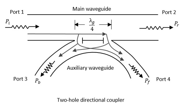
Key Parts Inside Explained
At its core, a directional coupler is a carefully balanced set of conductive pathways designed to leak just the right amount of RF energy—not too much, not too little. The main players are two parallel transmission lines (usually microstrip or stripline) spaced 0.2 mm to 2 mm apart, with their lengths tuned to λ/4 (quarter-wavelength) at the target frequency. For a 2.4 GHz Wi-Fi coupler, that means 31.25 mm traces on FR4 PCB, while a 28 GHz mmWave version shrinks to 2.68 mm. Get this wrong by ±10%, and coupling efficiency drops 30% or more.
The substrate material is critical—cheap FR4 (εᵣ=4.3, loss tangent 0.02) works for 1–3 GHz consumer devices, but its ±1.5 dB performance drift from -20°C to 80°C makes it useless in automotive radar (requires -40°C to 125°C stability). High-end couplers use Rogers RO4350B (εᵣ=3.48, loss tangent 0.0037), cutting insertion loss to 0.1 dB/cm at 10 GHz and holding ±0.2 dB coupling stability across temperature swings. For 40 GHz test gear, alumina ceramic (εᵣ=9.8) is the gold standard, with 0.05 dB/cm loss but at 5x the cost of PCB versions.
Precision spacing between lines is non-negotiable. A 10 dB coupler might need 1.0 mm spacing ±0.05 mm—any wider, and coupling drops 2 dB; any tighter, and it risks arcing at 50 W power levels. Some designs use air gaps (εᵣ=1.0) for mmWave, where 0.1 mm dimensional errors cause 15% frequency shifts. The conductors themselves matter too: 1 oz copper (35 µm thick) handles 5 A current at 2 GHz, but mmWave couplers switch to 0.5 oz copper (17.5 µm) to reduce skin effect losses by 40% at 30 GHz.
Resonant stubs are often added to sharpen frequency response. A 2 GHz coupler might include 18.75 mm open-circuit stubs (λ/4 at 2 GHz) to suppress harmonics above 6 GHz by 20 dB. Without these, a +30 dBm (1 W) input could bleed -10 dBm (0.1 mW) of noise into sensitive receivers. Some aerospace couplers integrate ferrite-loaded absorbers to dump unwanted modes, keeping VSWR <1.15:1 even with 60% reflected power.
Port terminations make or break performance. A 50-ohm coupler with 52-ohm load resistors introduces 0.1 dB measurement errors, while cheap 5% tolerance resistors can cause 1 dB ripple across frequency. The best lab-grade units use thin-film resistors (0.1% tolerance, ±25 ppm/°C drift), ensuring ±0.05 dB flatness from DC to 40 GHz. For high-power radars (500 W+), termination resistors must dissipate 5 W continuously without drifting >0.5% in value—ordinary 0805 SMDs would cook themselves in 30 seconds.
Shielding prevents crosstalk. A plastic-housed 6 dB coupler might pick up -40 dB of nearby 5 GHz interference, but a cast aluminum enclosure suppresses this to -70 dB. In dense phased arrays, even 0.5 dB of stray coupling between adjacent couplers can distort beam steering by 3°. Some military designs spend $200+ per unit on hermetic gold-plated shields to survive salt fog and 50G vibration.
The solder joints are a hidden failure point. A 0.3 mm void in a BGA connection increases resistance by 20 mΩ, which seems trivial—until you realize it causes 0.2 dB loss at 10 GHz. Hand-soldered prototypes often show ±0.5 dB performance scatter, while reflow-processed boards tighten this to ±0.1 dB. For space applications, joints are X-ray inspected to guarantee <0.1% voids after 500 thermal cycles (-65°C to +125°C).
Every millimeter and milliohm in these parts is optimized for one goal: siphoning off an exact fraction of signal power without distorting the rest. Cut corners on materials or tolerances, and your “directional” coupler becomes an expensive attenuator with unpredictable behavior. That’s why a 5 PCB coupler works for garage door openers, but satellite comms demand 500 units with every parameter locked down to ±1%.
Why Direction Matters
Directional couplers aren’t just power splitters—they’re signal traffic cops, designed to measure forward and reflected waves separately with precision. A 20 dB coupler with 30 dB directivity can distinguish between a 50 W transmit signal and a 0.05 W reflection (0.1% of power), crucial for detecting antenna faults before they cause 3 dB loss (50% power drop) in a cell tower. Without directionality, you’d get ±2 dB measurement errors—enough to mask a bad cable with 1.8:1 VSWR in a 5G small cell.
The physics comes down to wave interference timing. When two transmission lines run parallel for λ/4 (e.g., 7.5 mm at 10 GHz), forward waves add constructively at the coupled port (+20 dB), while reflected waves cancel destructively (-10 dB). Poor directivity (<15 dB) means 10% of reflected power contaminates forward measurements, turning a 1% reflection into a 1.1% reading—a 10% error that could hide a developing amplifier fault.
| Scenario | Low Directivity (15 dB) | High Directivity (30 dB) |
|---|---|---|
| 5G PA Monitoring | Misses 2% VSWR shifts | Catches 0.5% VSWR changes |
| Cable Fault Detection | Needs 3 dB loss to trigger alarm | Sees 0.5 dB impedance mismatches |
| Lab Signal Analysis | ±1 dB harmonic distortion errors | ±0.1 dB measurement precision |
| Radar Echo Processing | 20% false positives in clutter | 2% false positive rate |
| Cost Impact | $5 (consumer grade) | $50+ (aerospace grade) |
Material choices directly affect directionality. A PTFE-based coupler maintains 30 dB directivity ±1 dB from -55°C to 125°C, while FR4 PCB versions degrade to 15 dB at 85°C. For mmWave automotive radar (77 GHz), silicon substrates with 0.1 µm trace precision achieve 35 dB directivity, but cost 200/unit versus 20 for 24 GHz radar couplers.
Impedance discontinuities kill directionality. A 50-ohm coupler with a 55-ohm connector reflects 4% of power, reducing effective directivity by 6 dB. High-end solutions use tapered transitions (0.1 mm to 0.5 mm width gradients) to maintain 1.15:1 VSWR (96% power transfer), preserving >28 dB directivity across octave bandwidths.
Phase matching is critical. At 28 GHz, just 0.1 mm length mismatch between coupled lines introduces 10° phase error, dropping directivity 8 dB. Aerospace couplers use laser-trimmed delay lines to keep phase alignment within ±2°, ensuring 32 dB directivity for satellite payload testing.
Real-world impact? In fiber DAS (Distributed Antenna Systems), a 25 dB directivity coupler can pinpoint failing RF connectors by detecting 0.2 dB reflection changes—preventing $50,000+ tower downtime. Meanwhile, SDR (Software Defined Radio) prototypes using 15 dB directivity couplers suffer 30% EVM (Error Vector Magnitude) degradation from undetected reflections.
Frequency dictates requirements. A 6 GHz Wi-Fi 6E coupler needs 25 dB directivity to isolate -40 dBm noise from +20 dBm transmit power, while sub-1 GHz IoT devices get by with 18 dB—saving $3/unit in BOM costs.
Directionality isn’t optional—it’s what separates a useful measurement tool from an expensive attenuator. A $10 coupler with 20 dB directivity works for garage door openers, but mission-critical comms demand 30+ dB, even at 10x the price. Because when 1% measurement errors can mean dropped calls for 1,000 users or a missed missile warning, direction isn’t just important—it’s everything.
Common Uses in Systems
Directional couplers are the unsung heroes of RF systems, quietly working behind the scenes to monitor, control, and optimize signal flow across countless applications. In a 5G base station, a 20 dB coupler might tap off 1% of the 100 W transmit power (1 W) to monitor amplifier health, while in a satellite uplink, a 30 dB coupler samples just 0.1% of a 500 W signal (0.5 W) to verify modulation accuracy without wasting precious energy. These components are everywhere—from 10 Wi-Fi routers to 10M radar systems—because they solve a critical problem: how to measure RF signals without disturbing them.
”A directional coupler is like a stethoscope for RF engineers—it lets you listen to the heartbeat of a system without cutting the wires.”
In cellular networks, directional couplers play a 24/7 watchdog role. A macro cell might use six 10 dB couplers (one per sector) to continuously monitor VSWR on each antenna port, triggering alarms if reflections exceed 5% (1.3:1 VSWR)—a sign of water ingress or connector corrosion. When a 3 dB loss (50% power drop) occurs due to a failing antenna, the coupler detects it within 100 ms, preventing dropped calls for 5,000+ users. The cost? About 50 per coupler, but the alternative—20,000 in truck rolls and tower downtime—makes it a no-brainer.
Test and measurement gear relies on high-directivity (>30 dB) couplers to avoid measurement corruption. A vector network analyzer (VNA) uses a dual-directional coupler to separate forward (S21) and reflected (S11) waves with ±0.1 dB accuracy. Without this, a 2% impedance mismatch could appear as 5% in the data, leading to $100,000+ in faulty PCB redesigns. For EMC testing, couplers with 40 dB directivity isolate -60 dBm radiated emissions from +30 dBm test signals, ensuring compliance with FCC Part 15 limits.
”In RF design, what you don’t measure can cost you six figures in respins. Directional couplers are the insurance policy.”
Radar systems push couplers to their limits. A phased array radar might use 200+ 15 dB couplers (one per element) to monitor amplifier phase coherence across the array. If one element drifts 5° in phase, the coupler detects the 0.2 dB amplitude change, allowing real-time correction before beam pointing errors exceed 0.5°. Military radars demand hermetically sealed couplers that survive 50G shocks and -55°C to +125°C swings, costing 300+ each but preventing 2M system failures.
Even consumer devices benefit. A Wi-Fi 6 router uses a 6 dB coupler to sample 25% of the transmit signal for adaptive power control. If the EVM (Error Vector Magnitude) degrades by 3% due to interference, the coupler helps the system boost power 2 dB automatically—maintaining 800 Mbps throughput instead of dropping to 400 Mbps. The coupler adds $0.30 to the BOM, but avoids 30% more support calls.
Medical RF systems like MRI machines use ultra-low-loss (<0.05 dB) couplers to monitor 1 kW+ RF pulses without distorting ppm-level frequency stability. A 0.5 dB coupler error could shift proton resonance by 0.1 ppm, blurring images enough to hide 2 mm tumors. That’s why these couplers cost $500+—cheaper than a malpractice lawsuit.
From preventing dropped calls to catching cancer early, directional couplers prove their worth daily. They’re not glamorous, but when 1 dB of error can mean 1,000 angry customers or 1 missed diagnosis, their 5-500 price tag is the best investment an engineer can make.
Picking the Right One
Choosing a directional coupler isn’t about finding the “best” one—it’s about matching specs to your exact needs while balancing cost, performance, and reliability. A 5G base station might need a 20 dB coupler with ±0.5 dB flatness across 3.4–3.8 GHz, while a Wi-Fi 6 router can get by with a cheaper 10 dB coupler (±2 dB variance) for 5.1–5.8 GHz. Get this wrong, and you could waste $50,000/year in unnecessary component costs or suffer 30% higher signal distortion.
| Parameter | Consumer Grade | Industrial Grade | Aerospace Grade |
|---|---|---|---|
| Frequency Range | 0.8–6 GHz (±15%) | 1–18 GHz (±5%) | DC–40 GHz (±1%) |
| Coupling Accuracy | ±2 dB | ±0.5 dB | ±0.1 dB |
| Directivity | 15 dB | 25 dB | 35 dB |
| Power Handling | 10 W | 50 W | 500 W |
| Temp Stability | -20°C to +85°C (±2 dB) | -40°C to +125°C (±0.5 dB) | -55°C to +150°C (±0.2 dB) |
| Price Range | 3–20 | 50–200 | 300–1,000 |
Frequency dictates your first cut. A sub-6 GHz 5G coupler needs to cover 3.3–4.2 GHz with <1.5:1 VSWR, while a mmWave radar coupler must handle 24–40 GHz with ultra-low loss (<0.1 dB/mm). Cheaper FR4 PCB couplers work below 6 GHz, but Rogers laminate or ceramic becomes mandatory at 28 GHz+, adding 5–10x to the cost.
Coupling factor is about signal-to-noise tradeoffs. A 30 dB coupler (0.1% tap) is great for 500 W radar monitoring, but its -30 dBm output might drown in noise for IoT sensors. Conversely, a 6 dB coupler (25% tap) gives a strong -10 dBm signal but steals too much power from low-noise amplifiers. For most RFID readers, 15–20 dB hits the sweet spot—1–3% tap with >20 dB SNR.
Directivity separates useful data from garbage. In a cellular repeater, 15 dB directivity means 10% of reflected power contaminates measurements—fine for VSWR alarms but useless for precise load tuning. A PA feedback loop needs >25 dB to keep harmonics <-50 dBc. The rule? Every 3 dB increase in directivity cuts measurement error by 50% but adds 10–100 to the price.
Environmental specs make or break reliability. A plastic-housed coupler fails after 500 thermal cycles in a car roof antenna, while a hermetic ceramic version survives 5,000 cycles. Salt spray testing reveals more: aluminum enclosures corrode after 200 hours, but gold-plated Invar lasts 2,000+ hours in marine environments—critical for offshore radar.
Don’t overpay—but don’t cheap out. A 5 coupler in a 10M satellite risks 500K in launch delays if it drifts 1 dB in orbit. Yet spending 300 on a lab-grade coupler for a $50 IoT sensor is insanity. Match the coupler’s lifespan to your product: 1–3 years for smartphones, 10+ years for infrastructure.
Sample before committing. Even identically spec’d couplers vary: batch A might have 0.3 dB better flatness than batch B. Test 10+ units across temperature extremes—a 1,000 test budget can prevent 100K in field failures.
The right coupler doesn’t just work—it disappears into your system, providing invisible, flawless performance at the lowest possible cost. Spend time here, or spend 10x more fixing mistakes later.


