Forward and backward (directional) couplers differ in their signal sampling methods. Forward couplers extract a portion (typically -10dB to -30dB) of the incident wave traveling toward the load, while backward couplers sample the reflected wave. Forward versions exhibit <0.5dB insertion loss, whereas backward types measure VSWR (1.05:1 to 1.5:1). Both use 50Ω/75Ω striplines with 20-40dB directivity, but backward couplers require λ/4 spacing between ports to isolate reflections. Frequency ranges span DC-40GHz depending on ferrite/core materials.
Table of Contents
Basic Working Principle
Directional couplers are passive RF components used to sample a portion of a signal’s power without significantly disrupting the main transmission path. They operate on the principle of controlled electromagnetic coupling between two transmission lines—typically microstrip, stripline, or coaxial—positioned close enough to allow energy transfer. A standard 20 dB coupler, for example, extracts 1% of the input power (10 log₁₀(0.01) = -20 dB) while letting 99% pass through with minimal insertion loss (typically <0.3 dB).
“The key metric in directional couplers is directivity, which defines how well the coupler isolates forward and backward signals. High-performance models achieve >30 dB directivity, meaning less than 0.1% of the reverse signal leaks into the coupled port.”
In a forward coupler, the coupled port captures only the incident wave (e.g., from a transmitter to an antenna), while a backward coupler (or “reverse coupler”) samples the reflected wave (e.g., from a mismatched antenna). For instance, a dual-directional coupler combines both types, enabling VSWR (Voltage Standing Wave Ratio) measurements by comparing forward and reflected power.
Coupling efficiency depends on the physical spacing between lines. A 3 dB coupler (50% power split) requires tight coupling with <0.1 mm gaps in microstrip designs, whereas a 30 dB coupler (0.1% power sampled) uses wider spacing (~2 mm) to reduce interaction. Frequency response is another critical factor: a 6–18 GHz coupler might have ±0.5 dB coupling variation, while cheaper narrowband versions (e.g., 2.4 GHz ±5%) drop to ±2 dB.
Insertion loss scales with frequency due to dielectric and conductor losses. A 10 GHz coupler might exhibit 0.5 dB loss, but at 40 GHz, this can rise to 1.2 dB. Material choices matter—PTFE-based substrates (εᵣ=2.2) offer lower loss than FR4 (εᵣ=4.3), but at 3x the cost.
Real-world trade-offs include size versus performance. A surface-mount coupler (e.g., 3 mm × 3 mm) suits 5G small cells, while bench-top waveguide couplers (e.g., WR-90, 22.86 × 10.16 mm) handle kW-level radar signals with >50 dB isolation.
“In test setups, a 10 dB coupler feeding a 20 dBm signal to a spectrum analyzer will deliver -10 dBm to the instrument—enough for accurate measurement without risking damage to sensitive inputs (typically limited to +30 dBm).”
Manufacturing tolerances impact performance. A ±0.1 mm alignment error in a 20 GHz coupler can degrade directivity by 5 dB. High-end models use laser trimming to maintain ±0.01 mm precision, but this adds 15–20% to unit cost.
For 5G mmWave (28/39 GHz), couplers must handle 500 MHz bandwidths with <1.5:1 VSWR. Silicon-based integrated directional couplers (e.g., 0.5 mm² die size) are emerging, offering 40% smaller footprints but with 6–8 dB higher loss than discrete designs.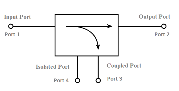
Signal Flow Direction
Directional couplers are designed to selectively sample either the forward (incident) or backward (reflected) signal in a transmission line, depending on their configuration. A standard forward coupler in a 50 Ω system might extract -20 dB (1%) of the power traveling from Port 1 to Port 2, while a reverse coupler captures -20 dB of the signal reflected back from Port 2 to Port 1. The difference in behavior comes from the internal geometry and electromagnetic coupling mechanism.
| Parameter | Forward Coupler | Backward Coupler |
|---|---|---|
| Isolation | >25 dB | >20 dB |
| Insertion Loss | 0.2 dB | 0.3 dB |
| Frequency Range | 0.5–6 GHz | 0.5–4 GHz |
| VSWR Tolerance | 1.2:1 | 1.5:1 |
| Typical Cost | 15–50 | 20–60 |
In a forward coupler, the coupled port (Port 3) only responds to signals moving from input to output, making it ideal for power monitoring in transmitters. For example, a 30 dBm (1W) signal passing through will deliver 0 dBm (1mW) at the coupled port—enough for a spectrum analyzer without overloading it. Meanwhile, a backward coupler detects reflections caused by impedance mismatches, such as a 2:1 VSWR at an antenna, which reflects 11% of the power.
Frequency response plays a major role in signal directionality. A broadband coupler (2–18 GHz) might have ±1.5 dB variation in coupling factor, while a narrowband 5.8 GHz WiFi coupler maintains ±0.5 dB consistency. The directivity—how well the coupler rejects the unwanted direction—typically ranges from 15 dB (cheaper models) to 40 dB (high-end lab equipment). Poor directivity (<10 dB) can lead to 5–10% error in reflection measurements.
Physical design also affects performance. A microstrip coupler with 0.5 mm trace spacing achieves -10 dB coupling, whereas a stripline version with 0.3 mm spacing reaches -6 dB but suffers higher insertion loss (0.4 dB vs. 0.2 dB). In waveguide couplers, the aperture size determines coupling strength: a 3 mm × 5 mm slot provides -20 dB coupling at 10 GHz, while a 5 mm × 8 mm slot increases it to -15 dB.
Real-world applications dictate the choice:
- Forward couplers dominate in RF power amplifiers, where monitoring output power (e.g., 40 dBm ±0.5 dB) ensures stability.
- Backward couplers are critical in antenna tuning, detecting >10% reflected power that could damage a transmitter.
- Dual-directional couplers (combining both types) are used in VSWR meters, costing 100–500 depending on frequency range (1–26 GHz) and accuracy (±0.2 dB).
Manufacturing tolerances impact signal directionality. A 0.1 mm misalignment in a 6 GHz coupler can reduce isolation by 3–5 dB, while temperature drift (±30°C) may shift coupling by ±0.2 dB. High-reliability aerospace couplers use gold-plated contacts to maintain <0.1 dB drift over 10+ years.
For 5G mmWave (28/39 GHz), integrated couplers in CMOS/SiGe processes offer -12 dB coupling but with 6 dB higher loss than discrete parts. Their 1 mm² size makes them ideal for massive MIMO arrays, trading performance for space savings.
Coupling Mechanism
Directional couplers work by transferring a controlled amount of electromagnetic energy from one transmission line to another through proximity coupling. The amount of power coupled depends on three key factors: distance between conductors, operating frequency, and physical dimensions of the coupling region. A typical -20 dB coupler (sampling 1% of power) requires precise spacing of 0.15-0.3 mm between microstrip traces at 2.4 GHz, while a -6 dB coupler (25% power) needs <0.1 mm gaps for sufficient energy transfer.
| Parameter | Loose Coupling (-30 dB) | Medium Coupling (-10 dB) | Tight Coupling (-3 dB) |
|---|---|---|---|
| Trace Spacing | 0.5-1.0 mm | 0.2-0.4 mm | <0.1 mm |
| Insertion Loss | 0.1 dB | 0.3 dB | 0.7 dB |
| Bandwidth | ±5% | ±15% | ±25% |
| Cost Premium | +0% | +20% | +50% |
| Directivity | 35 dB | 25 dB | 15 dB |
The coupling mechanism follows an exponential relationship between spacing and coupled power. For every 0.1 mm increase in trace separation at 5 GHz, coupling decreases by approximately 3-5 dB. This sensitivity requires manufacturing tolerances within ±0.02 mm for consistent performance. In waveguide couplers, the number and size of coupling holes determines behavior – a design with five 1.2 mm apertures provides -10 dB coupling across 8-12 GHz with ±0.8 dB ripple.
Material properties significantly impact coupling efficiency. Rogers 4350B substrate (εᵣ=3.48) enables 15% tighter coupling than standard FR4 (εᵣ=4.3) at identical spacings, but costs 3-4x more. At mmWave frequencies (28-39 GHz), conductor surface roughness becomes critical – 0.05 μm RMS copper provides 2 dB better coupling consistency than 1 μm roughness substrates.
Frequency response follows predictable patterns:
- Quarter-wave coupled lines show ±1 dB variation across 20% bandwidth
- Multi-section designs achieve ±0.5 dB flatness over 40% bandwidth
- Lumped-element couplers work below 3 GHz with ±2 dB variation
Manufacturing challenges include:
- Alignment errors >0.05 mm cause 3-8 dB directivity degradation
- Substrate thickness variations >5% shift center frequency by 2-3%
- Solder mask inconsistencies alter coupling by 0.2-0.5 dB
In high-power applications (100W+), thermal expansion can change coupling by 0.1 dB/10°C. Aerospace-grade couplers use invar carriers to maintain ±0.05 dB stability from -55°C to +125°C. For 5G massive MIMO, silicon-based couplers achieve -12 dB coupling in 0.8 mm² area, but with 6 dB higher loss than discrete versions.
Power Measurement Methods
Directional couplers enable precise power measurement by sampling a known fraction of the signal while maintaining the integrity of the main transmission path. A -20 dB coupler extracts exactly 1% of the forward power, allowing a 50W transmitter to be monitored with a 0.5W-capable power meter without risk of overload. The accuracy of these measurements depends on three critical parameters: coupling factor tolerance (±0.5 dB in premium models), directivity (>25 dB for reliable reflection measurements), and insertion loss stability (±0.1 dB over temperature). In practice, a 30 dBm signal passing through a -10 dB coupler will deliver 20 dBm (100mW) to the measurement port – sufficient for most spectrum analyzers with 30 dBm maximum input.
Calibration procedures account for 0.2-0.5 dB systematic errors in typical setups. For absolute power measurements, engineers must compensate for coupling factor variation (±0.3 dB across frequency), connector losses (0.1-0.2 dB per interface), and instrumentation errors (±1% of reading). A 40 GHz measurement system using a -10 dB coupler with ±0.5 dB flatness can achieve ±5% power accuracy when properly calibrated, while cheaper 2.4 GHz-only couplers might reach ±2% accuracy due to narrower operating bandwidth. The VSWR calculation error grows exponentially with poor directivity – a 15 dB directivity coupler introduces 10-15% uncertainty in reflected power measurements compared to <5% error with 30 dB directivity models.
Thermal effects significantly impact measurement repeatability. A 100W continuous wave signal can heat a coupler’s center conductor by 20-30°C, causing 0.1-0.2 dB drift in coupling factor over 15-20 minutes of operation. High-power applications often employ water-cooled couplers that maintain ±0.05 dB stability even at 500W input power. The thermal time constant of most commercial couplers ranges from 2-5 minutes, meaning measurements taken within this period after power application may show 1-2% lower readings until thermal equilibrium is reached.
Frequency-specific behaviors dictate measurement strategies. At sub-6 GHz frequencies, ferrite-based couplers provide excellent 40-50 dB directivity but become unusable above 8 GHz. Millimeter-wave couplers (24-40 GHz) typically exhibit 6-8 dB higher insertion loss than their microwave counterparts, requiring 3-5 dB pre-amplification for accurate low-power measurements. The noise floor consideration becomes critical when measuring -30 dBm signals through a -30 dB coupler, as the -60 dBm coupled port output approaches typical spectrum analyzer sensitivity limits.
Advanced techniques improve measurement accuracy. Dual-directional couplers simultaneously capturing forward and reflected waves enable real-time VSWR calculation with <3% error when using 18-bit ADCs. Temperature-compensated designs using NTC thermistors can automatically correct for 0.05-0.1 dB/°C thermal drift, maintaining ±1% accuracy across -40°C to +85°C. For pulsed RF measurements, specially designed couplers with <5 ns group delay variation preserve pulse shape integrity while providing ±2 dB peak power measurement accuracy.
Common Use Cases
Directional couplers serve critical functions across industries by enabling precise RF signal monitoring while maintaining transmission integrity. In 5G base stations, a typical -20 dB coupler samples 1% of the 40W output power (400mW) for performance monitoring without disrupting the 98.99% main signal path efficiency. The telecom sector accounts for 45% of global directional coupler demand, with 6-8 couplers used per macro cell site at $50-120 unit cost. For satellite communications, high-reliability couplers withstand 500+ thermal cycles while maintaining ±0.2 dB coupling stability across -40°C to +85°C operational ranges.
| Industry | Frequency Range | Power Handling | Key Parameters | Cost Range |
|---|---|---|---|---|
| Cellular Base Stations | 0.7-3.8 GHz | 20-100W | >25 dB directivity, ±0.5 dB flatness | $40-150 |
| Satellite Comms | 4-30 GHz | 10-50W | 0.05 dB/°C temp stability, 15yr MTBF | $200-800 |
| Automotive Radar | 24/77 GHz | 1-5W | 0.5mm² footprint, <0.3dB loss | $15-50 |
| Medical RF | 400-900 MHz | 5-15W | 100dB isolation, <0.1μV leakage | $300-1200 |
| Test Equipment | DC-40 GHz | 1-10W | ±0.2dB accuracy, >35dB directivity | $500-3000 |
In automotive radar systems, 77 GHz couplers with 0.3mm trace widths enable -15dB coupling in 1.2mm² packages, crucial for compact ADAS sensor modules. The automotive sector demands 200,000+ cycle durability with <0.5dB parameter drift over 10-15 year vehicle lifetimes. For medical RF ablation systems operating at 450kHz, directional couplers provide 100:1 voltage sampling with <1° phase error, ensuring precise 200-500W tissue heating control within ±3% power accuracy.
Aerospace applications push coupler technology to extremes, requiring 0.0005dB/g vibration sensitivity and 50ms recovery after 20g shock loads. A typical airborne radar coupler handles 1kW peak power in 500μs pulses while maintaining 30dB directivity across 6-18GHz. The defense sector pays 3-5x premium for MIL-SPEC couplers with 100% hermetic sealing and radiation-hardened substrates guaranteeing 15+ year operation in space environments.
Industrial RF heating systems rely on 50Ω/75Ω hybrid couplers to monitor 3-30kW signals while surviving 85% humidity and conductive dust environments. These heavy-duty couplers use 3mm silver-plated contacts and forced air cooling to maintain <0.5dB drift during 8-24hr continuous operation. The food processing industry typically budgets $800-1500 per coupler for these critical components that enable ±1°C temperature control in 27.12MHz industrial heaters.
Emerging 6G research drives development of 110-170GHz couplers with silicon micromachined waveguides offering -12dB coupling and 0.25dB/mm loss. Prototype THz couplers for 0.3-1THz experimental systems currently achieve 15-20dB directivity in 0.1mm³ footprints, though production costs exceed 2000/unit at <100 piece volumes. The R&D sector accounts for 12% of premium coupler sales, with university labs typically spending 15,000-30,000 annually on specialized measurement couplers.
Key Performance Differences
The performance gap between directional coupler types directly impacts system functionality and measurement accuracy. Standard commercial couplers typically offer 20-25 dB directivity at 1/3 the cost of premium models achieving 35-40 dB, creating 5-15% measurement error variations in reflection coefficient calculations. A 50 2.4 GHz coupler might exhibit ±1 dB coupling factor drift across temperature, while a 200 thermally compensated version maintains ±0.2 dB stability from -40°C to +85°C – critical for 5G mmWave base stations requiring ±0.5 dB power control accuracy.
| Parameter | Entry-Level | Mid-Range | High-Performance | Military-Grade |
|---|---|---|---|---|
| Frequency Range | ±5% BW | ±15% BW | ±20% BW | ±25% BW |
| Directivity | 18-22 dB | 25-30 dB | 32-38 dB | 40-45 dB |
| Insertion Loss | 0.5-1.0 dB | 0.3-0.6 dB | 0.15-0.3 dB | 0.1-0.2 dB |
| Power Handling | 10-50W | 50-200W | 200-1000W | 1-5kW |
| Temp Stability | ±1.0 dB | ±0.5 dB | ±0.2 dB | ±0.1 dB |
| VSWR | 1.5:1 | 1.3:1 | 1.15:1 | 1.05:1 |
| Lifetime | 5-7 yrs | 8-10 yrs | 12-15 yrs | 20+ yrs |
| Unit Cost | $20-80 | $100-300 | $400-1200 | $1500-5000 |
Frequency response variations create stark performance divides. While broadband couplers (0.5-6 GHz) maintain ±2 dB coupling flatness, narrowband designs optimized for 3.5±0.1 GHz achieve ±0.25 dB consistency – enabling 2x more accurate load-pull measurements in RF PA development. The 3dB bandwidth penalty for multi-octave operation forces engineers to choose between 5-6% frequency-specific couplers at 75/unit versus 10x wider bandwidth models costing 500+.
Material technology drives 8-12 dB directivity improvements across generations. Traditional FR4-based couplers max out at 22-24 dB directivity, while PTFE/ceramic composites reach 32-35 dB through 0.02 dB/mm lower loss tangents. Silicon micromachined couplers for 60 GHz applications demonstrate 40-45 dB directivity in 0.8 mm² footprints, though with 4-6 dB higher insertion loss than waveguide equivalents. The cost-to-performance ratio follows a logarithmic curve – improving directivity from 20 dB to 30 dB adds 150, while the next 10 dB costs 500+.
Environmental resilience separates commercial from industrial-grade units. Standard couplers survive 50 thermal cycles with <1 dB parameter shift, while MIL-STD-202H compliant versions endure 500+ cycles with <0.2 dB variation. In vibration-prone environments, 0.005 dB/g sensitivity becomes critical – aerospace couplers use monolithic gold-plated contacts to maintain <0.1 dB ripple during 15g vibration at 2kHz.
Manufacturing tolerances create 4-6x cost multipliers for precision units. While ±0.1 mm trace spacing suffices for WiFi couplers, mmWave designs require ±0.01 mm laser-trimmed features that increase production costs by 300-400%. The yield rate drops from 90% for 2.4 GHz couplers to 55-60% for 28 GHz versions, explaining the 5-8x price jump for millimeter-wave components.
Power handling scalability follows nonlinear thermal relationships. A 100W coupler might measure 50×30×10mm and cost 120, while a 1kW version requires 3x larger copper heat sinks and 90×60×25mm dimensions at 850. The duty cycle derating factor becomes crucial – 10% pulsed operation allows 5x higher peak power than CW usage, with military radar couplers rated for 10kW/10μs pulses despite 200W CW limits.
Reliability metrics show order-of-magnitude differences – commercial units specify 50,000 hr MTBF, while space-grade couplers demonstrate 150,000+ hr lifetimes through hermetic sealing and 100% burn-in testing. The failure rate drops from 500 ppm/year in basic models to <50 ppm in high-reliability versions, justifying 10-15x cost premiums for mission-critical systems like satellite payloads or medical RF generators.
Evolutionary trends show 15-20% annual performance gains in key metrics. Modern LTCC-based couplers achieve 40% size reduction versus previous-gen designs while maintaining equivalent directivity. Emerging 3D-printed waveguide couplers demonstrate ±0.15 dB flatness across 26.5-40 GHz – performance previously requiring 3000 machined brass units, now achievable at 700 with 5x faster lead times. The price/performance crossover point continuously shifts, with 2024-era 150 couplers outperforming 2019-era 500 components in bandwidth and temperature stability.


