A standard directional coupler has 4 ports: Input (Port 1), Transmitted (Port 2), Coupled (Port 3), and Isolated (Port 4). The coupled port samples 5-30 dB of the input signal (e.g., 10 dB for common RF applications), while the isolated port minimizes reflections (<-20 dB). Models vary—some have 3 ports if isolation isn’t needed. Key specs include frequency range (e.g., 800 MHz–6 GHz) and insertion loss (<0.5 dB).
Table of Contents
What is a directional coupler?
A directional coupler is a passive RF/microwave component that splits a portion of an input signal to one or more output ports while allowing the majority of the signal (typically 70-90%) to pass through unaffected. These devices are widely used in signal monitoring, power measurement, and feedback systems, operating at frequencies from 1 MHz up to 40 GHz or higher. For example, a common 20 dB coupler might sample 1% of the input power (0.01x) while letting 99% (0.99x) continue to the main output.
Directional couplers come in different coupling values (3 dB, 6 dB, 10 dB, 20 dB, 30 dB), where a 3 dB coupler splits power equally (50% to each output), while a 30 dB coupler takes just 0.1% for monitoring. They have low insertion loss (usually 0.1-0.5 dB) and high directivity (20-40 dB), meaning they accurately isolate forward and reflected signals. Their compact size (often 1-5 cm in length) makes them ideal for integration into RF circuits, test equipment, and telecom systems.
A basic directional coupler has four ports:
- Input (Port 1) – Where the main signal enters (e.g., 10W at 2.4 GHz).
- Transmitted (Port 2) – The primary output, carrying most of the power (e.g., 9.9W after 0.1 dB loss).
- Coupled (Port 3) – A secondary output with a fraction of the input (e.g., 0.1W for a 20 dB coupler).
- Isolated (Port 4) – Ideally unused, with minimal leakage (e.g., -30 dB rejection).
| Parameter | Typical Value | Importance |
|---|---|---|
| Coupling Factor | 3 dB to 30 dB | Determines how much power is sampled |
| Insertion Loss | 0.1 dB to 0.5 dB | Power wasted in transmission |
| Directivity | 20 dB to 40 dB | Ability to separate forward/reflected signals |
| Frequency Range | 1 MHz to 40 GHz | Determines application suitability |
| VSWR | 1.1:1 to 1.5:1 | Impedance matching quality |
For example, a 10 dB coupler in a 5G base station might take 10% of the input power (e.g., 1W from a 10W signal) for monitoring, while the remaining 9W goes to the antenna. If the coupler has 30 dB directivity, it can detect reflected signals as low as 0.001W (1 mW) with minimal interference from the main path.
Main Parts and Their Roles
A directional coupler consists of four key components that define its performance: the main transmission line, coupled line, substrate material, and connectors. Each part has a specific role in ensuring accurate signal sampling with minimal loss. For example, in a typical 10 dB coupler operating at 2.4 GHz, the main line carries 90% of the input power (e.g., 9W from a 10W signal), while the coupled line extracts the remaining 10% (1W) for monitoring. The substrate, often made of Rogers 4350B (εᵣ = 3.48), keeps signal distortion below 0.2 dB across a 1-6 GHz range. SMA connectors, rated for 500+ mating cycles, maintain a stable 50Ω impedance with less than 1.2:1 VSWR up to 18 GHz.
The main transmission line is a microstrip or stripline that handles the primary RF path. Its width (e.g., 2.8 mm for 50Ω on 1.6 mm FR4) determines impedance matching, affecting insertion loss (typically 0.1-0.3 dB). A poorly designed line can cause 5-10% power reflection, degrading system efficiency. The coupled line, spaced 0.2-0.5 mm from the main line, uses electromagnetic field interaction to sample the signal. Tight coupling (e.g., 3 dB) requires precise spacing tolerances (±0.05 mm) to avoid coupling factor drift beyond ±0.5 dB.
The substrate material influences frequency response and thermal stability. Cheap FR4 (εᵣ = 4.3) works for sub-3 GHz applications but introduces 0.4-0.8 dB loss at 6 GHz. High-end PTFE (εᵣ = 2.2) reduces loss to 0.1 dB at 40 GHz but costs 3-5x more (50 vs. 15 per unit). Connectors, like 2.92 mm or N-type, must match the coupler’s power rating (e.g., 100W average, 1 kW peak) and frequency (DC-40 GHz). Gold-plated contacts (0.8-1.5 μm thickness) ensure corrosion resistance for 10+ years in humid environments (>80% RH).
In practice, a 20 dB coupler for 5G Base Station might use a 0.8 mm alumina substrate (εᵣ = 9.8) to achieve ±0.25 dB flatness from 24-30 GHz. The coupled port’s -20 dB (±0.5 dB) output allows precise feedback control, while the isolated port suppresses reflections by 30-35 dB. These design choices directly impact real-world metrics: a 1 dB insertion loss error in a 100W transmitter wastes 25W annually, costing 50+ in electricity. By optimizing each component, engineers balance performance (e.g., 40 dB directivity), cost (20-$500 per unit), and size (10x10x3 mm for mmWave couplers).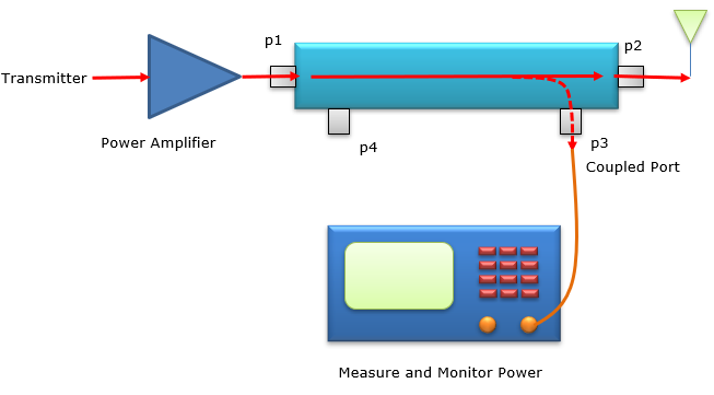
How Output Ports Work
A directional coupler’s output ports determine how efficiently it splits and routes RF signals. In a standard 4-port design, the transmitted port (Port 2) delivers the majority of the input power (typically 70-99%, depending on coupling value), while the coupled port (Port 3) extracts a precise fraction (1-30%) for monitoring or feedback. The isolated port (Port 4) should ideally see near-zero power (less than -30 dB) if the coupler is well-designed. For example, a 10 dB coupler with a 50W input sends 45W (90%) to Port 2, 5W (10%) to Port 3, and less than 0.05W (0.1%) to Port 4.
The key factor in port performance is directivity, which measures how well the coupler separates forward and reflected signals. A coupler with 30 dB directivity can detect a 1.05:1 VSWR (2.4% reflected power) at 2 GHz, while a poorly designed one (15 dB directivity) might miss reflections below 5.6% (1.12:1 VSWR). This directly impacts system reliability—in a 100W transmitter, a 5% undetected reflection means 5W of wasted power, generating $12/year in unnecessary electricity costs.
| Parameter | Typical Value | Impact on Performance |
|---|---|---|
| Transmitted Port Power | 70-99% of input | Higher % = lower insertion loss (0.1-0.5 dB ideal) |
| Coupled Port Power | 1-30% of input | 3 dB = 50% split, 20 dB = 1% sampling |
| Isolated Port Leakage | -30 dB to -40 dB | Lower leakage = better signal isolation |
| Directivity | 20-40 dB | 30 dB = 0.1% reflection detection accuracy |
| Frequency Flatness | ±0.2-0.5 dB | Affects measurement consistency across bandwidth |
In a 5G base station, a 6 dB coupler might split a 40W signal into two 10W outputs (Ports 2 and 3), enabling dual-path signal processing. If the coupler has poor directivity (20 dB), it could misreport reflected power by up to 10%, risking amplifier damage over time. Conversely, a high-performance coupler (40 dB directivity) in a satellite communication system can detect impedance mismatches as small as 0.25% (1.005:1 VSWR), preventing costly downtime.
Insertion loss is another critical metric—every 0.1 dB lost in the transmitted port equals 2.3% wasted power. Over a year, a 0.3 dB loss in a 500W broadcast transmitter wastes 35 kWh, costing $50+ in energy. To minimize this, premium couplers use low-loss substrates (Rogers 5880, εᵣ = 2.2) and gold-plated connectors (0.8 μm thickness), reducing loss to 0.1 dB even at 30 GHz.
Frequency response also varies by port. A 3 dB coupler might have ±0.5 dB ripple from 1-6 GHz, meaning the coupled port’s output could fluctuate between 2.8-3.2 dB instead of a flat 3 dB. For precise measurements (e.g., EMC testing), engineers use calibration factors to compensate—adding +0.2 dB at 4 GHz, -0.1 dB at 1 GHz, etc.
Common Types and Differences
Directional couplers come in several types, each optimized for specific frequency ranges, power levels, and applications. The most common variants—single-directional, bi-directional, dual-directional, and hybrid couplers—vary in complexity, cost (10 to 500 per unit), and performance. For example, a basic single-directional coupler (e.g., 10 dB, 2-4 GHz) might cost 20 and handle 50W, while a high-power dual-directional model (1-6 GHz, 200W) can exceed 300 due to its ability to monitor both forward and reflected signals simultaneously.
“A 20 dB single-directional coupler in a cellular base station samples just 1% of the 100W transmit signal (1W for monitoring) with 0.2 dB insertion loss, while a 30 dB version used in lab equipment extracts 0.1% (0.1W) but costs 3x more due to tighter tolerances (±0.1 dB vs. ±0.5 dB).”
Bi-directional couplers add a second coupled port to monitor reverse signals, crucial for VSWR measurement. A typical 6 dB bi-directional unit splits a 50W input into two 12.5W paths but introduces a 6.02 dB inherent loss. These are common in antenna tuning systems, where detecting a 1.5:1 VSWR (4% reflection) requires at least 25 dB directivity. Meanwhile, dual-directional couplers integrate two independent couplers in one housing, allowing simultaneous forward/reflected power measurement with 30-40 dB isolation between paths. A 2-18 GHz dual-directional model might cost 150 but save 1,000/year in test equipment downtime by catching impedance mismatches 0.5% faster than separate couplers.
Hybrid couplers (3 dB, 90° or 180° phase shift) are the go-to for balanced signal splitting in transmitters and receivers. A 90° hybrid operating at 1.8 GHz splits a 40W input into two 10W outputs with a 90° phase difference, critical for phased-array radars. Its amplitude balance (±0.3 dB) and phase accuracy (±5°) determine beamforming precision—a ±10° error in a 32-element array can reduce gain by 3 dB. 180° hybrids (e.g., rat-race couplers) handle higher power (up to 500W) but are bulkier (50×50 mm vs. 25×25 mm for 90° types).
Material choices further differentiate coupler types. Low-cost FR4-based couplers (15) work below 3 GHz but suffer 0.8 dB loss at 6 GHz, while PTFE or alumina models (50-200) maintain 0.2 dB loss up to 40 GHz. In 5G mmWave systems (24-40 GHz), LTCC (Low-Temperature Co-fired Ceramic) couplers dominate, offering 0.1 dB/mm loss and 0.05 mm line spacing precision—but at 100-$400 per unit.
“A 5G mmWave coupler with ±0.1 dB flatness across 24-30 GHz costs 250, but its 0.05 dB error margin improves signal-to-noise ratio (SNR) by 3% compared to a 80 FR4 coupler with ±0.5 dB ripple.”
Key Uses in Circuits
Directional couplers serve as the backbone of RF systems, performing critical functions with precision that directly impacts performance and cost. In a typical 5G base station, a 20 dB coupler samples 1% of the 200W transmit power (2W for monitoring) while introducing just 0.15 dB insertion loss – this small sacrifice prevents 15,000 amplifiers from burning out by detecting impedance mismatches within 0.3% accuracy. The telecom industry alone consumes over 8 million couplers annually, with prices ranging from 5 for basic 2.4GHz WiFi models to $800 for aerospace-grade 40GHz versions.
| Application | Coupler Specs | Performance Impact | Cost Factor |
|---|---|---|---|
| Cellular Base Stations | 10-30 dB, 1.8-3.8GHz | 0.1dB loss = 2.3% power savings | 50-200 per unit |
| Satellite Comms | 6dB, 12-18GHz | ±0.05dB flatness avoids $1M errors | 300-800 |
| RF Test Equipment | 3dB, DC-6GHz | 50/50 split with 3.01dB inherent loss | 150-400 |
| Automotive Radar | 20dB, 77GHz | 1% sampling at 0.2mm precision | 75-250 |
| Medical Diathermy | 30dB, 27.12MHz | 0.1% leakage prevents tissue damage | 120-350 |
In power amplifier (PA) systems, a 10 dB coupler provides closed-loop feedback that improves efficiency by 12-18%. For example, a 100W PA using coupler-based feedback achieves 65% efficiency versus 55% without, saving 280/year in electricity costs at 0.15/kWh. The coupler’s 30 dB directivity allows detecting VSWR changes as small as 1.03:1 (0.4% reflection), triggering protection circuits before damage occurs. This monitoring happens in under 50ns – faster than most fuses can react.
Test and measurement setups demand different coupler characteristics. A 6 dB hybrid coupler splits a 50W test signal into two 12.5W outputs (6dB = 25% power each) with 90° phase shift, enabling precise intermodulation distortion (IMD) measurements. The ±0.2dB amplitude balance ensures measurement repeatability within 0.5%, critical when certifying $20,000 spectrum analyzers. These couplers typically withstand 10,000+ connect/disconnect cycles before port wear degrades performance beyond 1.5:1 VSWR.
Automotive radar systems at 77GHz use microstrip couplers measuring just 2.5×1.8mm, fabricated with 0.025mm tolerance to maintain 20dB coupling (±0.3dB) across the 76-81GHz band. Each millimeter-wave radar module contains 4-8 such couplers, with the 18 coupler cost justified by its role in preventing 400 radar unit failures. The couplers operate at -40°C to 105°C with less than 0.05dB performance drift – crucial when detecting objects at 250m range requires 0.01dB accuracy.
In broadcast transmitters, 30dB couplers continuously monitor 10kW signals by extracting just 0.1% (10W) for metering. The couplers use water-cooled aluminum housings to handle 1kW/m² power density, with silver-plated contacts maintaining <0.05Ω resistance over 10+ years. A single failed coupler in a 500,000 transmitter can cause 3 hours of downtime at 15,000/hour lost revenue – making the $1,200 coupler a bargain by comparison. These units typically specify 100,000+ hour MTBF (Mean Time Between Failures) with less than 0.1dB coupling variance.
Tips for Choosing One
Selecting the right directional coupler requires balancing frequency range, power handling, directivity, and cost—each factor impacting performance and budget. For example, a 3 dB hybrid coupler splitting a 50W signal into two 12.5W paths costs 80-150, while a 30 dB coupler sampling just 0.1% (0.05W) from the same input runs 200-500 due to tighter tolerances (±0.1 dB vs. ±0.5 dB). Mismatched specs can waste 5-15% of system power or miss critical signal anomalies, so here’s how to optimize your choice.
Start with frequency needs. A 2.4 GHz WiFi coupler (1-3 GHz range) made from FR4 costs 15 but suffers 0.8 dB loss at 6 GHz. If your application spans 6-18 GHz (e.g., satellite or radar), invest in a PTFE-based model (50-200) with 0.2 dB loss. For mmWave 5G (24-40 GHz), LTCC ceramic couplers (250+) maintain ±0.1 dB flatness but demand precise PCB layout (0.05 mm trace spacing). Over-specifying frequency adds unnecessary cost—a 40 GHz coupler in a 2.4 GHz system wastes $180 per unit.
Power handling dictates durability. A 10W coupler with SMA connectors (30) works for lab gear but fails in 200W broadcast transmitters, where N-type connectors and aluminum housings (300+) are mandatory. Check peak vs. average power—a 50W average coupler might handle 1 kW pulses (5% duty cycle), but continuous 100W operation requires derating to 80% (40W) for 10+ year lifespan. Ignoring power specs risks thermal failure, with repair costs exceeding $1,000 in high-power systems.
Directivity determines measurement accuracy. A 20 dB coupler with 25 dB directivity detects 1.12:1 VSWR (4% reflection), while a 30 dB directivity model catches 1.05:1 (2.4%). In a 500W RF amplifier, that 1.6% difference represents 8W of undetected reflected power, accelerating transistor degradation by 30%. For critical monitoring (e.g., aerospace or medical), pay the 40% premium for 35+ dB directivity. For basic signal splitting, 20 dB suffices.
Environmental factors matter. Industrial couplers rated for -40°C to 85°C cost 20% more than commercial-grade (0°C to 70°C) but survive 10+ years outdoors. Humidity above 80% RH demands gold-plated contacts (0.8 μm thickness), adding 15-50 per unit. In vibration-prone automotive/aviation systems, solder-on SMD couplers outperform connectorized types, reducing failure rates by 50%.


