
Wavange Compatibility, Fast Assembly, Signal Integrity
A waveguide quick disconnect should not be selected only because it can be opened without conventional flange bolts. A reliable assembly must perform three functions

Waveguide Pressure Inlet Selection | Gas Connection, Pressure Control, Moisture Protection<
A waveguide pressure inlet should be selected as part of a complete pressurization system, not as an isolated threaded port. The inlet must match the

Waveguide Bulkhead Feedthrough Selection | Barrier Mounting, Pressure Sealing, Flange Alignment
A waveguide bulkhead feedthrough should not be selected by waveguide size alone. It is simultaneously an RF transmission interface, a mechanical penetration through a wall

Manual vs Electric Waveguide Switches | Control, Speed, Reliability
Mechanical Positioning Power-Off Operation Project Context The internal linkage mechanism positions the waveguide channel at the selected port. This mechanical switching action does not depend

Waveguide Power Handling | Continuous Wave Power and Peak Power, Breakdown Limits, Cooling
Waveguide power handling capability is the primary indicator for the selection of microwave systems. Exceeding the power limit causes breakdown discharge inside the waveguide, leading
Waveguide Frequency Bands Chart | WR Sizes, Cutoff Frequency, Applications
Waveguides provide low-loss and high-power signal transmission for microwave and millimeter-wave systems. A waveguide frequency bands chart helps engineers compare WR sizes, operating frequency ranges,

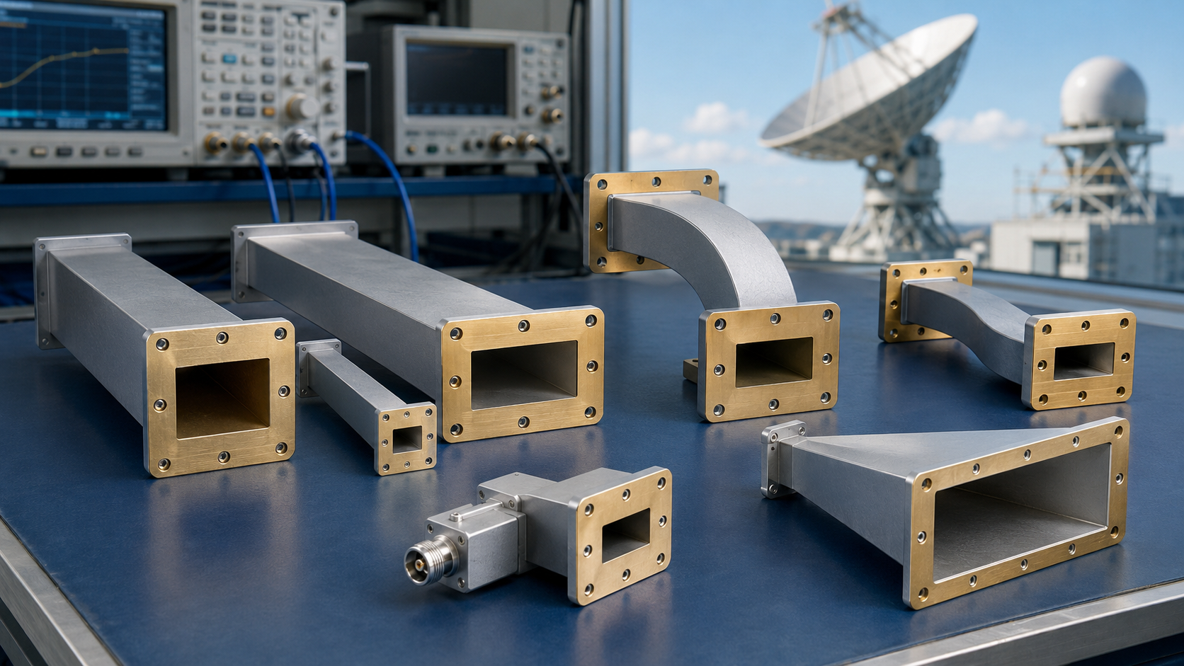
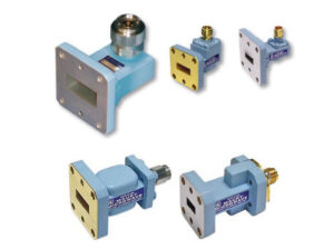
Waveguide Flange Size Guide | EIA Standard, IEC Types, Gasket Fit
When selecting waveguide flanges, the biggest pitfall I’ve encountered is that for the same WR model, the EIA and IEC systems share nearly identical inner

Ku-Band Satellite Antenna Selection | Weather Fade, High Throughput, Dish Size
Ku-band procurement should lock onto 1.2-meter antennas to reserve a 5dB rain fade margin. HTS requires LNBs with a 0.2dB low noise figure. Utilizing AGC

Flat Panel Satellite Antenna Technology | Metamaterials, Electronic Steering, LEO
Flat-panel satellite antennas utilize metamaterials for electronically controlled scanning, with a thickness of only 5cm and millisecond-level switching, perfectly adapted for LEO. Its ±60° wide-angle

Log Periodic Antenna Working Principle Explained | Broadband, Self-Similar Structure
Log-periodic antennas rely on self-similar structures to achieve extremely wideband coverage, such as from 30MHz to 3GHz. During fabrication, multiple dipoles must be arranged proportionally,

Log Periodic Antenna Design Guide | Frequency Range, Gain, Structure
Designing a log-periodic antenna requires first determining the coverage frequency band, with its operating frequency typically ranging between 30 MHz and 3 GHz. Its structure

Custom IoT Antenna Solutions | Power, Size, Connectivity
By precisely controlling return loss below -10dB, customized antennas significantly enhance signal transmission efficiency by 20% within a miniature size and effectively reduce system power

Custom 5G Antenna Solutions | High Bandwidth, MIMO, Latency
Leveraging our deep accumulation of RF technology, we provide customized 5G antenna solutions. By utilizing an advanced 4×4 MIMO architecture and supporting millimeter-wave (mmWave) bands,
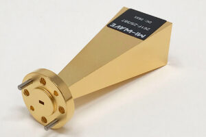
Horn Antenna Gain Calculation Guide | Formula, Aperture Area, Efficiency
Horn antenna gain is determined by the aperture area, operating wavelength, and efficiency (typically taken as 0.6). The calculation formula is: 4π multiplied by the
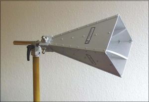
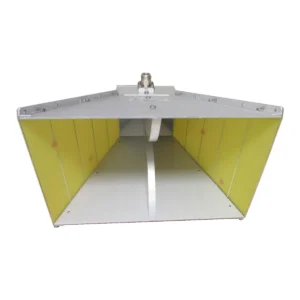
Standard Gain Horn Antenna Selection Guide | Frequency, Gain, VSWR
Selection depends on matching the frequency (e.g., 2-40 GHz), ensuring gain error < ±0.5 dB and VSWR < 1.3. Understanding Frequency Each horn antenna corresponds
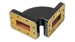
Flexible Waveguide Selection Guide | Size, Frequency, Bend Radius
Selection should be based on frequency to determine size, for example, WR-90 corresponds to 8.2-12.4 GHz; During installation, strictly control the E-plane static bend radius
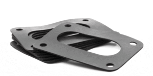
Waveguide Conductive Gasket Selection Guide | Structure, Performance, Price
Waveguide conductive gaskets typically use silicone rubber filled with silver or nickel particles, with a standard thickness of about 0.69mm, capable of providing shielding effectiveness
Design of Conductive Elastomer Waveguide Gaskets | Function, Material, Manufacturing Process
Function: Achieve waveguide sealing and electromagnetic shielding (X-band 8-12GHz, shielding effectiveness ≥60dB). Material: Silicone rubber matrix + 3-5wt% carbon nanotubes (CNT), tensile strength ≥5MPa. Process:
How to Test Broadband Waveguide Antenna Performance
Test broadband waveguide antennas via VNA calibrated with WR-90 standards, measuring S11 (<-10dB) from 26.5-40GHz. In far-field (15λ away), compare with a reference antenna to
Why Choose Waveguide Components for EMC
Waveguide components enhance EMC with ultra-low insertion loss (<0.2dB at 10GHz) and robust shielding; precision-machined metal walls (roughness <0.8μm) suppress leakage, confining signals via mode

How to Install Open Ended Waveguides in Indoor Satellites
Align open-ended waveguides via laser tools (±0.1mm accuracy), seal flanges with 0.5mm silicone gel, torque bolts to 5N·m, then test VSWR (<1.2) to ensure indoor


