+86 29 8881 0979

default

What is the role of waveguide duplexers in communication systems

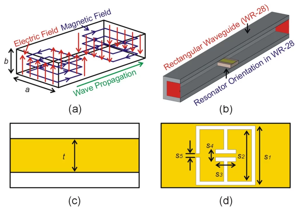
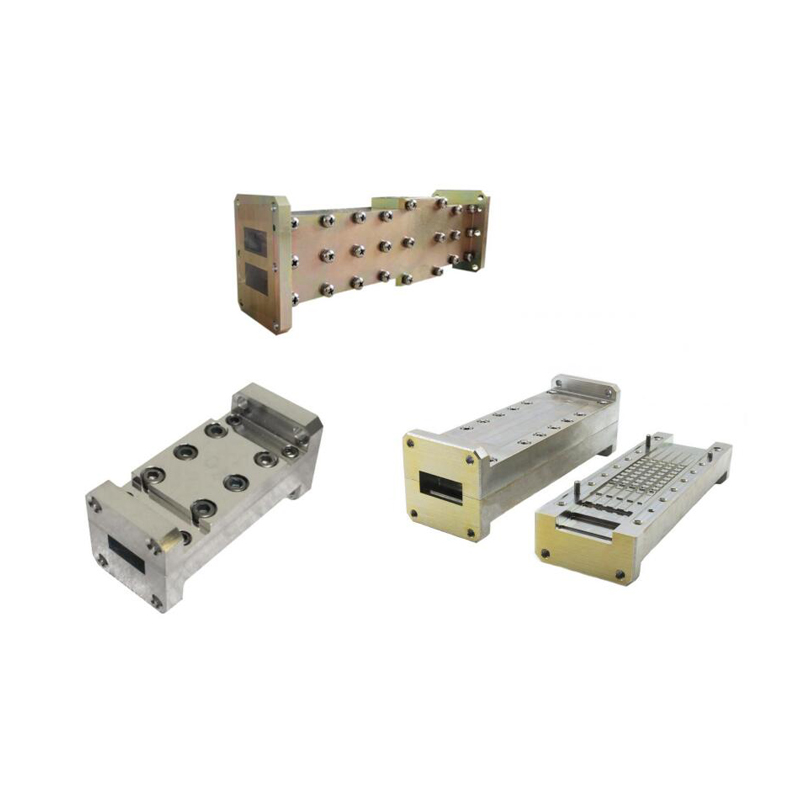
Waveguide duplexers are crucial for allowing a single antenna to simultaneously transmit and receive signals, often operating in frequency ranges like 3.5-4.2 GHz. They use internal filters to provide high isolation, typically over 30 dB, preventing powerful transmitted signals from overwhelming sensitive receivers, which is vital in radar and cellular systems. What is a Waveguide […]

What is the role of waveguide duplexers in communication systems Read More »

What are the 4 advantages of waveguide amplifiers over RF amplifiers

Waveguide amplifiers surpass RF amplifiers with higher frequency support (30-300GHz vs. <6GHz), lower insertion loss (<0.5dB vs. 1.2dB typical), 2-3× greater power capacity (100W+ vs. 20-30W), and broader bandwidth (>10GHz vs. ≤2GHz), optimizing high-frequency transmission efficiency. ​​Handles High Power Signals​​ While a typical coaxial-based RF amplifier might comfortably handle powers up to 500 watts, it

What are the 4 advantages of waveguide amplifiers over RF amplifiers Read More »

How to reduce insertion loss in waveguide assemblies

To reduce waveguide assembly insertion loss, optimize surface roughness (Ra≤0.2μm, cutting 30% loss vs. Ra=1μm), align with <λ/100 gap (e.g., <0.25mm in X-band for 15% reduction), and use low-loss materials like gold-plated copper to minimize resistive losses. Check Connector Alignment Studies indicate that a lateral offset of just ​​0.1 mm​​ in a standard WR-90 waveguide

How to reduce insertion loss in waveguide assemblies Read More »

What are the 6 critical waveguide assembly specifications

The six critical waveguide assembly specifications are operating frequency (e.g., 18-110 GHz), precise internal dimensions (±0.1 mm tolerance), low voltage standing wave ratio (VSWR <1.15:1), material (often aluminum or copper), surface finish (typically <1 µm Ra), and power handling capacity, which can exceed hundreds of kilowatts for pressurized systems. Operating Frequency Range The fundamental operating

What are the 6 critical waveguide assembly specifications Read More »

What are the 5 common waveguide antenna configurations

The five common waveguide antenna configurations include rectangular waveguides operating at 2–110 GHz, horn antennas achieving up to 25 dBi gain, slot arrays for precision radar systems, dielectric rod antennas for millimeter-wave applications, and parabolic reflectors often used with feed horns for high-directivity satellite communication exceeding 30 dBi. Rectangular Waveguide Basics From 5G base stations

What are the 5 common waveguide antenna configurations Read More »

How to design a waveguide antenna for high-frequency signals

Designing a high-frequency waveguide antenna requires precise calculation of its internal dimensions to support the desired propagation mode, typically using a width of at least 0.7λ for the dominant mode. Careful selection of low-loss materials like copper and rigorous simulation for impedance matching are critical to minimize signal attenuation and maximize power transfer efficiency. Understanding

How to design a waveguide antenna for high-frequency signals Read More »

What are the 5 main challenges in waveguide antenna manufacturing

The 5 main challenges in waveguide antenna manufacturing are maintaining precise internal surface roughness (often under 1µm), achieving tight dimensional tolerances (±0.05mm), managing complex assembly and alignment, selecting suitable high-cost materials like copper, and ensuring efficient heat dissipation for high-power applications. ​​Precise Dimension Control​​ Even a tiny error, say ​​a deviation of just 0.05 mm​​,

What are the 5 main challenges in waveguide antenna manufacturing Read More »

How does a waveguide antenna work in microwave systems

A waveguide antenna works by guiding high-frequency microwaves (e.g., 1-100 GHz) from a source to the radiating aperture with minimal loss. It functions as a precision transition, converting confined waveguide modes into free-space radiation, often achieving gains over 20 dBi for directional applications like radar or satellite communications. ​​What is a Waveguide?​​ They are crucial

How does a waveguide antenna work in microwave systems Read More »

How to test waveguide components for signal loss

To test waveguide components for signal loss, use a vector network analyzer (VNA) to measure insertion loss by comparing the transmitted signal power through the component to a known reference, typically aiming for losses below 0.1 dB in high-performance systems. Ensure proper flange alignment and calibration with thru-reflect-line (TRL) kits for millimeter-wave accuracy. ​​Understanding Signal

How to test waveguide components for signal loss Read More »

What are the 3 best materials for waveguide components

​For waveguide components, brass is a top choice for its excellent machinability and good conductivity, often used in experimental kits. Aluminum is favored for its light weight and natural corrosion resistance, making it ideal for outdoor antennas. Copper offers the highest electrical conductivity, crucial for low-loss systems, though it is more expensive. Each material is

What are the 3 best materials for waveguide components Read More »

Scroll to Top
Blank Form (#3)