Custom Antenna Solutions | 5 Industry-Specific Applications
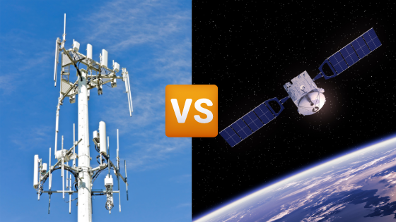
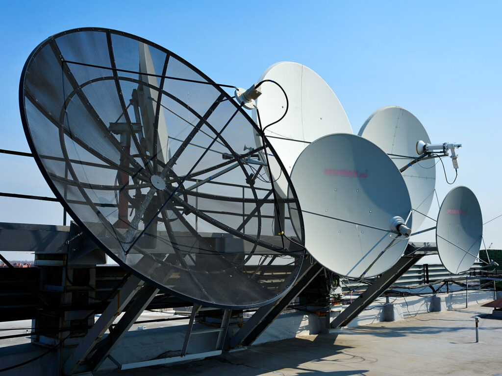
Customized antenna solutions are widely used in five major industries: communications (5G base station coverage increased by 30%), medical (MRI equipment signal enhanced by 25%), transportation (vehicle V2X communication reliability reaches 99.9%), industry (RFID reading distance increased to 15 meters), and aerospace (satellite communication gain increased by 5dB). Military Encryption Requirements At 3 AM, the […]
Custom Antenna Solutions | 5 Industry-Specific Applications Read More »