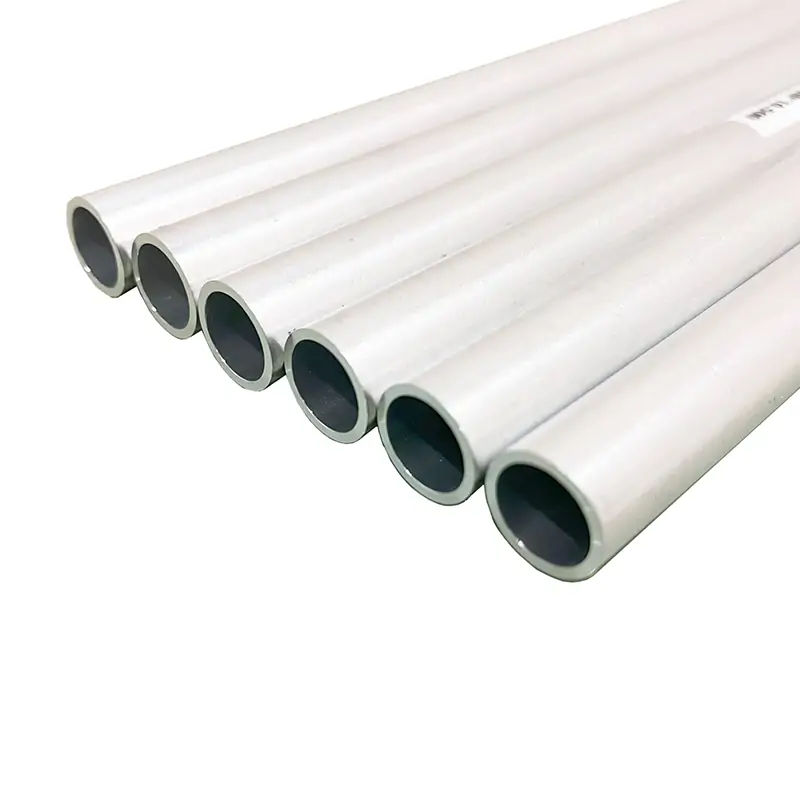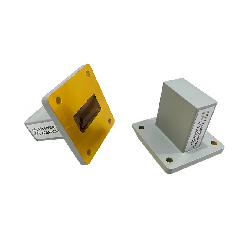
Waveguide Tube
A waveguide tube is a hollow metallic conduit used to direct and carry electromagnetic waves in microwave, radio frequency, and other communication systems. It supports efficient signal transmission over a range of frequencies, providing a controlled path with minimal loss and dispersion.
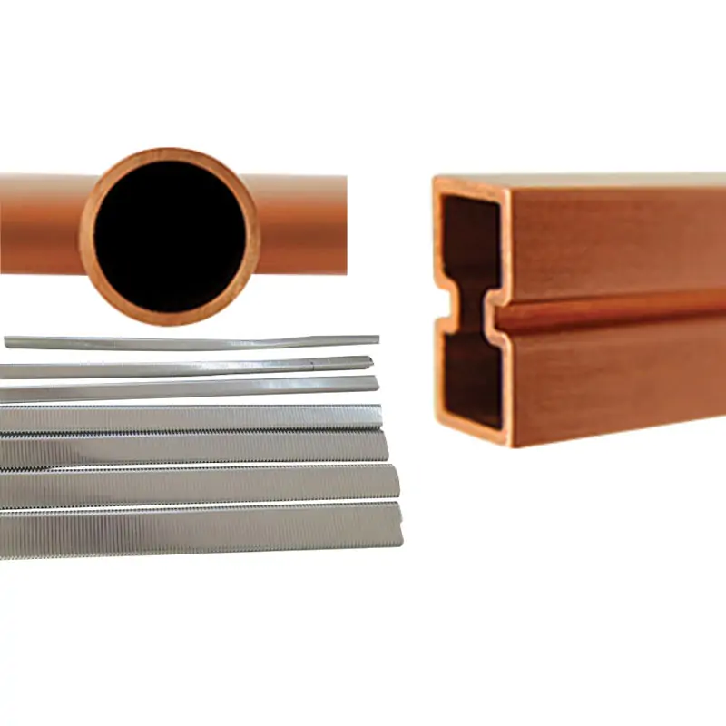
Dolph Microwave offers a premium selection of waveguide tubes, catering to a wide range of applications in microwave, radio frequency, and telecommunications systems. These tubes are available in sizes from WR2300 to WR10, making them versatile for various signal transmission needs. With options for standard, thin, and heavy wall thicknesses, Dolph Microwave ensures that each waveguide tube can be tailored to specific system requirements, providing efficient and reliable performance.
Key Features
- Broad Size Range: Covers waveguide sizes from WR2300 to WR10, accommodating a wide spectrum of frequency bands.
- Customizable Lengths: Offers lengths up to 3 meters, allowing for flexible installation and application.
- Material Options: Available in both Aluminum (Al) and Copper (Cu), catering to different environmental and performance needs.
- Wall Thickness Variety: Includes standard, thin, and heavy options to match the demands of various operational conditions.
- Precision Engineering: Each tube is meticulously crafted to ensure minimal loss and optimal signal integrity.
- High Conductivity: Materials chosen for their high electrical conductivity, enhancing signal transmission efficiency.
- Durability: Designed to withstand the rigors of both indoor and outdoor environments, ensuring long-term reliability.
Applications
Dolph Microwave’s waveguide tubes find applications in a myriad of fields, including:
- Telecommunications: Facilitating the transmission of data and voice signals over long distances with minimal loss.
- Radar Systems: Providing the structural pathway for high-frequency radar waves in both civil and military radar installations.
- Satellite Communications: Ensuring efficient signal routing between satellite dishes and communication equipment.
- Research and Development: Enabling precise and controlled signal transmission in scientific experiments and microwave testing.
- Aerospace: Supporting communication and navigation systems on aircraft and spacecraft with reliable signal paths.
Product Specifications
The following table highlights the specifications of Dolph Microwave’s waveguide tubes:
| Parameter | Specification |
|---|---|
| Waveguide Size | WR2300 to WR10 |
| Length | Up to 3 meters |
| Material | Aluminum (Al), Copper (Cu) |
| Wall Thickness | Standard, Thin, Heavy |
Dolph Microwave’s waveguide tubes stand out for their superior design, material quality, and customization options. Whether you’re setting up a complex telecommunications network, developing a sophisticated radar system, or conducting high-level scientific research, these waveguide tubes provide the reliability and performance needed for successful operations. By offering a range of sizes, materials, and wall thicknesses, along with the ability to customize lengths, Dolph Microwave ensures that every client can find the perfect waveguide tube to meet their specific requirements. For further information or to discuss customized solutions, Dolph encourages potential clients to reach out and engage with their team of experts.
| MODEL | FREQ. RANGE (GHz) | EIA STD. | IEC STD. | I.D A*B (mm) | O.D C*D (mm) | MATERIAL | ATTENUATION (LOW-HIGH) dB/Mtr. | PEAK POWER LOW-HIGH (MW) | CW POWER LOW-HIGH (MW) | DATASHEET | ||
| AL | CU | |||||||||||
| DH-3WT… | 0.32-0.49 | WR2300 | R3 | 584.2*292.1 | Al | 0.009-0.013 | DWG | STEP | ||||
| DH-4WT… | 0.35-0.53 | WR2100 | R4 | 533.4*266.7 | Al | 0.010-0.015 | DWG | STEP | ||||
| DH-5WT… | 0.41-0.62 | WR1800 | R5 | 457.2*228.6 | Al | 0.013-0.019 | DWG | STEP | ||||
| DH-6WT… | 0.49-0.75 | WR1500 | R6 | 381*190.5 | Al | 0.017-0.025 | DWG | STEP | ||||
| DH-8WT… | 0.64-0.98 | WR1150 | R8 | 292.1*146.05 | Al | 0.025-0.004 | DWG | STEP | ||||
| DH-9WT… | 0.76-1.15 | WR975 | R9 | 247.65*123.82 | Al | 0.003-0.005 | 93.81-133.7 | 196.4-295.4 | DWG | STEP | ||
| DH-12WT… | 0.96-1.46 | WR770 | R12 | 195.58*97.79 | Al | 0.005-0.007 | 59.67-84.18 | 117.6-173.2 | DWG | STEP | ||
| DH-14WT… | 1.13-1.73 | WR650 | R14 | 165.1*82.55 | 169.16*86.61 | Al/Cu | 0.006-0.009 | 0.007-0.010 | 41.34-59.74 | 88.45-135.7 | DWG | STEP |
| DH-18WT… | 1.45-2.2 | WR510 | R18 | 129.54*64.77 | 133.6*68.83 | Al/Cu | 0.008-0.013 | 0.010-0.015 | 26.19-37.00 | 53.19-78.34 | DWG | STEP |
| DH-22WT… | 1.72-2.61 | WR430 | R22 | 109.22*54.61 | 113.28*58.67 | Al/Cu | 0.011-0.016 | 0.013-0.019 | 18.23-26.26 | 30.03-45.20 | DWG | STEP |
| DH-26WT… | 2.17-3.3 | WR340 | R26 | 86.36*43.18 | 90.42*47.24 | Al/Cu | 0.016-0.023 | 0.019-0.027 | 11.87-16.44 | 18.50-26.60 | DWG | STEP |
| DH-32WT… | 2.6-3.95 | WR284 | R32 | 72.14*34.04 | 76.2*38.1 | Al/Cu | 0.021-0.031 | 0.025-0.037 | 7.645-10.85 | 11.42-16.69 | DWG | STEP |
| DH-40WT… | 3.22-4.9 | WR229 | R40 | 58.17*29.08 | 61.42*32.33 | Al/Cu | 0.028-0.042 | 0.034-0.050 | 5.475-7.549 | 7.659-10.79 | DWG | STEP |
| DH-48WT… | 3.94-5.99 | WR187 | R48 | 47.549*22.149 | 50.8*25.4 | Al/Cu | 0.040-0.059 | 0.048-0.070 | 3.296-4.697 | 4.397-6.340 | DWG | STEP |
| DH-58WT… | 4.64-7.05 | WR159 | R58 | 40.386*20.193 | 43.64*23.44 | Al/Cu | 0.049-0.072 | 0.058-0.086 | 2.792-3.719 | 3.574-4.783 | DWG | STEP |
| DH-70WT… | 5.38-8.17 | WR137 | R70 | 34.849*15.799 | 38.1*19.05 | Al/Cu | 0.066-0.095 | 0.078-0.114 | 1.975-2.531 | 1.768-3.122 | DWG | STEP |
| DH-84WT… | 6.57-9.99 | WR112 | R84 | 28.499*12.624 | 31.75*15.88 | Al/Cu | 0.091-0.131 | 0.108-0.156 | 1.284-1.702 | 1.523-1.958 | DWG | STEP |
| DH-100WT… | 8.2-12.5 | WR90 | R100 | 22.86*10.16 | 25.4*12.7 | Al/Cu | 0.126-0.182 | 0.150-0.217 | 0.758-1.124 | 0.817-1.180 | DWG | STEP |
| DH-120WT… | 9.84-15 | WR75 | R120 | 19.05*9.525 | 21.59*12.06 | Al/Cu | 0.151-0.222 | 0.180-0.265 | 0.622-0.903 | 0.627-0.898 | DWG | STEP |
| DH-140WT… | 11.9-18 | WR62 | R140 | 15.799*7.899 | 17.83*9.93 | Al/Cu | 0.199-0.294 | 0.238-0.351 | 0.457-0.633 | 0.502-0.683 | DWG | STEP |
| DH-180WT… | 14.5-22 | WR51 | R180 | 12.95*6.477 | 14.99*8.51 | Al/Cu | 0.269-0.396 | 0.320-0.473 | 0.312-0.433 | 0.323-0.445 | DWG | STEP |
| DH-220WT… | 17.6-26.7 | WR42 | R220 | 10.668*4.318 | 12.7*6.35 | Al/Cu | 0.426-0.607 | 0.507-0.723 | 0.171-0.246 | 0.174-0.237 | DWG | STEP |
| DH-260WT… | 21.7-33 | WR34 | R260 | 8.636*4.318 | 10.67*6.35 | Al/Cu | 0.493-0.728 | 0.588-0.868 | 0.139-0.209 | 0.131-0.188 | DWG | STEP |
| DH-320WT… | 26.3-40 | WR28 | R320 | 7.12*3.556 | 9.14*5.59 | Al/Cu | 0.660-0.974 | 0.787-1.162 | 96.0-146.0 KW | 109.7-160.1 KW | DWG | STEP |
| DH-400WT… | 32.9-50.1 | WR22 | R400 | 5.69*2.845 | 7.72*4.88 | Al/Cu | 0.923-1.362 | 1.100-1.624 | 64.4-97.0 KW | 68.89-101.4 KW | DWG | STEP |
| DH-500WT… | 39.2-59.6 | WR19 | R500 | 4.775*2.388 | 6.81*4.42 | Cu | 1.431-2.112 | 48.0-70.0 KW | 51.32-71.43 KW | DWG | STEP | |
| DH-620WT… | 49.8-75.8 | WR15 | R620 | 3.795*1.88 | 5.79*3.91 | Cu | 2.048-3.023 | 30.0-40.0 KW | 30.27-44.30 KW | DWG | STEP | |
| DH-740WT… | 60.5-91.9 | WR12 | R740 | 3.0988*1.5494 | 5.13*3.58 | Cu | 2.737-4.040 | 20.0-30.0 KW | 20.37-30.38 KW | DWG | STEP | |
| DH-900WT… | 73.8-112 | WR10 | R900 | 2.54*1.27 | 4.57*3.3 | Cu | 3.688-5.444 | 14.0-20.0 KW | 14.73-20.86 KW | DWG | STEP | |
| Part Number Guide: DH-100WT100A "100"—Waveguide Size | WR90 "WT"—Waveguide Type | Rectangle Waveguide Raw Tubes "100"— Length | 100 mm "A/C"— Material | Aluminium, Cu |
||||||||||||
| Note: Raw Waveguide in most alloys including Aluminum, OFHC, Copper, Brass, and more. Standard waveguide lengths are 2000mm. and we can cut waveguide to your dimensions on request. |
||||||||||||