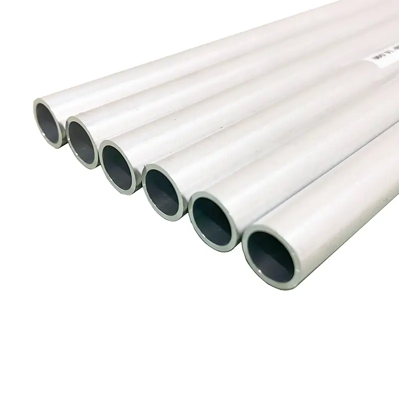
Waveguide Straights and Transitions
Waveguide straights and transitions are fundamental components in microwave systems, facilitating efficient signal propagation and enabling seamless connectivity between different waveguide sections or interfaces. These parts ensure minimal signal loss and are essential for maintaining the integrity and performance of communication and radar systems.
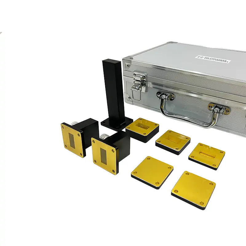
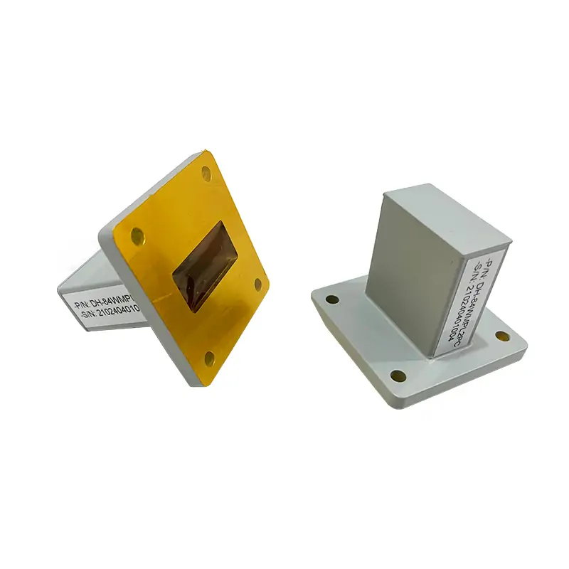
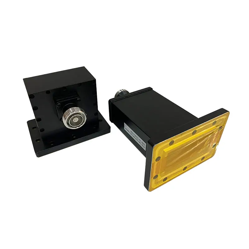
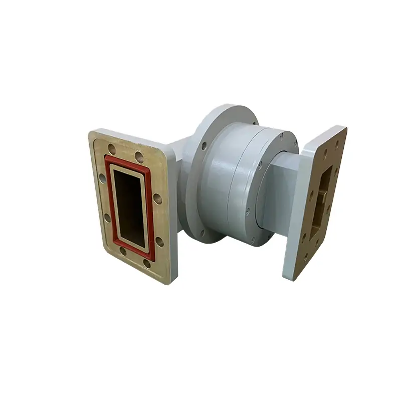
Dolph Microwave presents its advanced range of Double Ridged Waveguide Straights and Transitions, designed to cater to the specific needs of microwave and RF systems. These components are pivotal in ensuring efficient signal propagation and seamless connectivity within different sections of waveguide systems. Crafted with precision and high-quality materials, Dolph Microwave’s waveguide components offer exceptional performance for a wide array of applications.
Key Features
- Broad Waveguide Size Range: From WRD84 to WRD180, accommodating diverse system requirements.
- Flexible Length Options: Available in lengths of 100mm, 500mm, 1000mm, or custom lengths to fit specific installation needs.
- Material Selection: Manufactured in both Aluminum (Al) and Copper (Cu) to match different application environments and performance criteria.
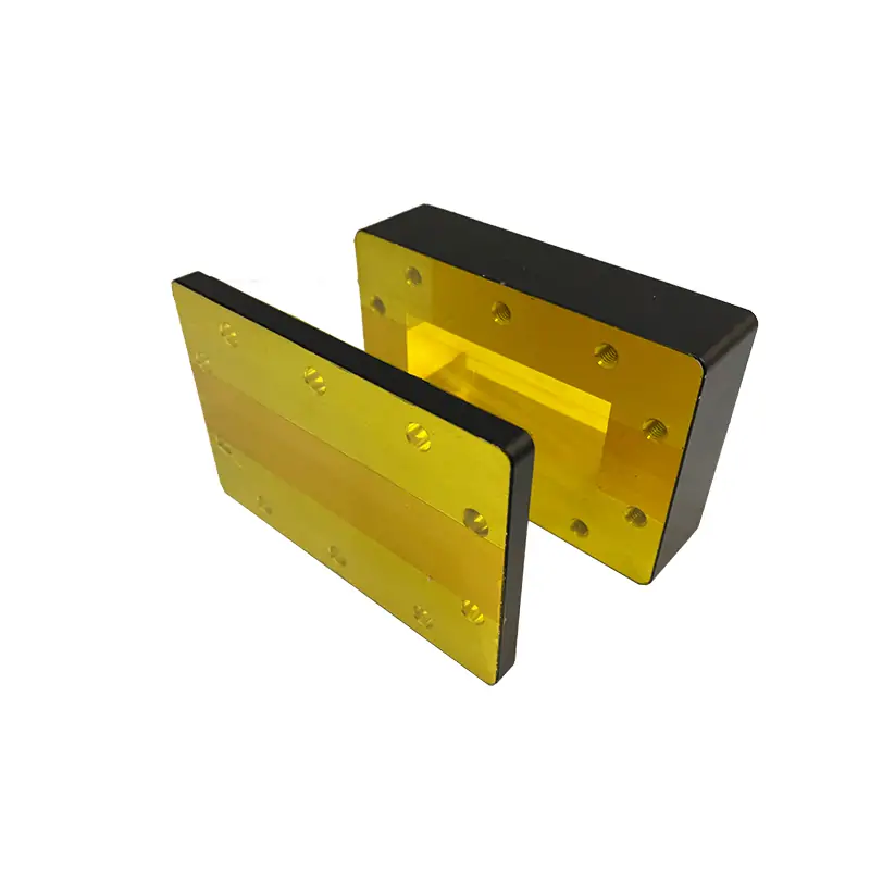
- Flange Types: Equipped with Cover and Grooved flanges, providing versatile connectivity options.
- High Power Handling: Engineered to manage high power levels, making them suitable for demanding applications.
- Optimal Performance: Designed to maintain high Voltage Standing Wave Ratio (VSWR) and minimal insertion loss, ensuring signal integrity.
- Customization Availability: Offers both standard and customized mechanical configurations, allowing for tailored solutions to meet unique system designs.
Applications
Dolph Microwave’s waveguide straights and transitions are essential in various high-frequency applications, including but not limited to:
- Telecommunications: Facilitating signal routing in complex communication networks.
- Radar Systems: Ensuring accurate signal transmission and reception in radar equipment.
- Satellite Communications: Providing reliable interconnections in satellite ground stations and uplink systems.
- Research and Development: Enabling precise measurements and experiments in microwave laboratories.
- Aerospace and Defense: Supporting critical communication and navigation systems in harsh environments.
Product Specifications
Here is a specification table that outlines the key attributes of Dolph Microwave’s waveguide straights and transitions:
| Parameter | Specification |
|---|---|
| Waveguide Size | WRD84 to WRD180 |
| Length (mm) | 100, 500, 1000 or custom |
| Material | Aluminum (Al), Copper (Cu) |
| Flange Type | Cover, Grooved |
| Power Handling | High |
| VSWR | High |
| Insertion Loss | Minimal |
Dolph Microwave’s waveguide straights and transitions stand out for their precision engineering, high-quality materials, and the ability to meet high power and performance demands. Whether for standard applications or customized projects, these components ensure efficient signal handling and connectivity, enhancing the overall performance of microwave and RF systems. For more information or to discuss specific requirements, Dolph encourages potential clients to reach out to their expert team, ready to provide support and tailored solutions.
| MODEL | FREQ. RANGE (GHz) | WG Size | VSWR | IL (dB/m) | FLANGES TYPE | LENGTH (mm) | MATERIAL | FINISH | ROHS & REACH | DATASHEET | ||
| COVER | GROOVED | |||||||||||
| DH-840DRWAL… | 0.84-2.0 | WRD840 | 1.15:1 | 0.2 | FPWRD840U24 | FMWRD840U24 | Up to 1500 | Al/Cu | Chromate/Painted | Comply | STEP | |
| DH-150DRWAL… | 1.5-3.6 | WRD150 | 1.15:1 | 0.15 | FPWRD150D24 | FMWRD150D24 | Up to 1500 | Al/Cu | Chromate/Painted | Comply | STEP | |
| DH-200DRWAL… | 2.0-4.8 | WRD200 | 1.15:1 | 0.15 | FPWRD200D24 | FMWRD200D24 | Up to 1500 | Al/Cu | Chromate/Painted | Comply | STEP | |
| DH-250DRWAL… | 2.6-7.8 | WRD250 | 1.15:1 | 0.15 | FPWRD250D30 | FMWRD250D30 | Up to 1500 | Al/Cu | Chromate/Painted | Comply | STEP | |
| DH-350DRWAL… | 3.5-8.2 | WRD350 | 1.15:1 | 0.25 | FPWRD350D24 | FMWRD350D24 | Up to 1500 | Al/Cu | Chromate/Painted | Comply | STEP | |
| DH-475DRWAL… | 4.75-11.0 | WRD475 | 1.15:1 | 0.2 | FPWRD475D24 | FMWRD475D24 | Up to 1500 | Al/Cu | Chromate/Painted | Comply | STEP | |
| DH-500DRWAL… | 5.0-18.0 | WRD500 | 1.15:1 | 0.5 | FPWRD500D36 | FMWRD500D36 | Up to 1500 | Al/Cu | Chromate/Painted | Comply | STEP | |
| DH-580DRWAL… | 5.8-16.0 | WRD580 | 1.15:1 | 0.35 | FPWRD580D28 | FMWRD580D28 | Up to 1500 | Al/Cu | Chromate/Painted | Comply | STEP | |
| DH-650DRWAL… | 6.5-18.0 | WRD650 | 1.15:1 | 0.35 | FPWRD650D28 | FMWRD650D28 | Up to 1500 | Al/Cu | Chromate/Painted | Comply | STEP | |
| DH-700DRWAL… | 7.0-18.5 | WRD700 | 1.15:1 | 0.4 | FPWRD700D26 | FMWRD700D26 | Up to 1500 | Al/Cu | Chromate/Painted | Comply | STEP | |
| DH-750DRWAL… | 7.5-18.0 | WRD750 | 1.15:1 | 0.6 | FPWRD750D24 | FMWRD750D24 | Up to 1500 | Al/Cu | Chromate/Painted | Comply | STEP | |
| DH-110DRWAL… | 11.0-26.5 | WRD110 | 1.2:1 | 0.75 | FPWRD110C24 | FMWRD110C24 | Up to 1500 | Al/Cu | Chromate/Painted | Comply | STEP | |
| DH-180DRWAL… | 18.0-40.0 | WRD180 | 1.2:1 | 1.5 | FPWRD180C24 | FMWRD180C24 | Up to 1500 | Al/Cu | Chromate/Painted | Comply | STEP | |
| Part Number Guide: DH-840DRWAL100PMA "840DR"—Waveguide Size | WRD840 "WAL"—Waveguide Type | Straight Waveguide "100"— Length | 100 mm "P"— Flange Type | Rectangular Flat "M"— Flange Type | Rectangular Grooved "A/C"— Material | Aluminium, Cu |
||||||||||||
| Note: All Dolph-MW models include an surtec/corrosion protection treatment and are painted flat black. Flanges are unplated, polished and surtec. Other finishes and paint colors are available upon request. |
||||||||||||