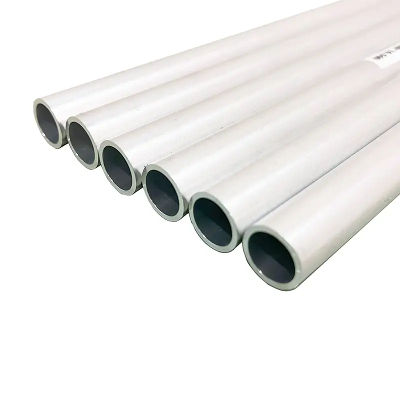
Circular Waveguide Tubing
Dolph Microwave Circular Waveguide Tubing delivers industry-leading performance in TE₁₁ mode with customizable internal diameters (51.99–2.388 mm). Optimized for ultra-low conductor loss in TE₀₁ mode—where attenuation decreases at higher frequencies—it enables efficient long-distance transmission. Featuring dual-polarization support and structural symmetry, these components are essential for radar rotary joints, antenna feeders, resonant cavities, and 5G backhaul systems. All waveguides achieve ≤1.03:1 VSWR and are available in aluminum, OFHC copper, or brass.
Product Description:
Dolph Microwave specializes in manufacturing premium Circular Waveguide Tubing engineered for the TE₁₁ mode, supporting frequencies from 3.89 GHz to 116 GHz. With customizable internal diameters ranging from 51.99 mm down to 2.388 mm, our waveguides offer tailored solutions for high-demand scenarios. While their bandwidth is narrower than comparable rectangular waveguides, they excel in low-loss, high-frequency transmission—particularly in the TE₀₁ mode, where conductor loss decreases with rising frequency, making them ideal for long-distance signal integrity.
Key Features
- Ultra-Low Loss: Optimized for TE₀₁ mode propagation, achieving loss reduction at higher frequencies (e.g., <0.05 dB/m in critical bands) for efficient long-range transmission.
- Dual-Polarization Support: Maintains signal integrity for orthogonally polarized waves, essential for dual-polarization antenna feeders and polarization-sensitive systems.
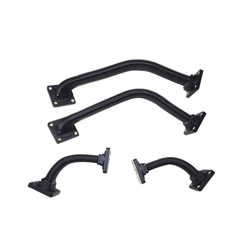
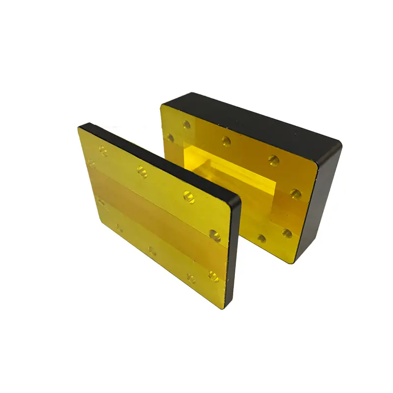
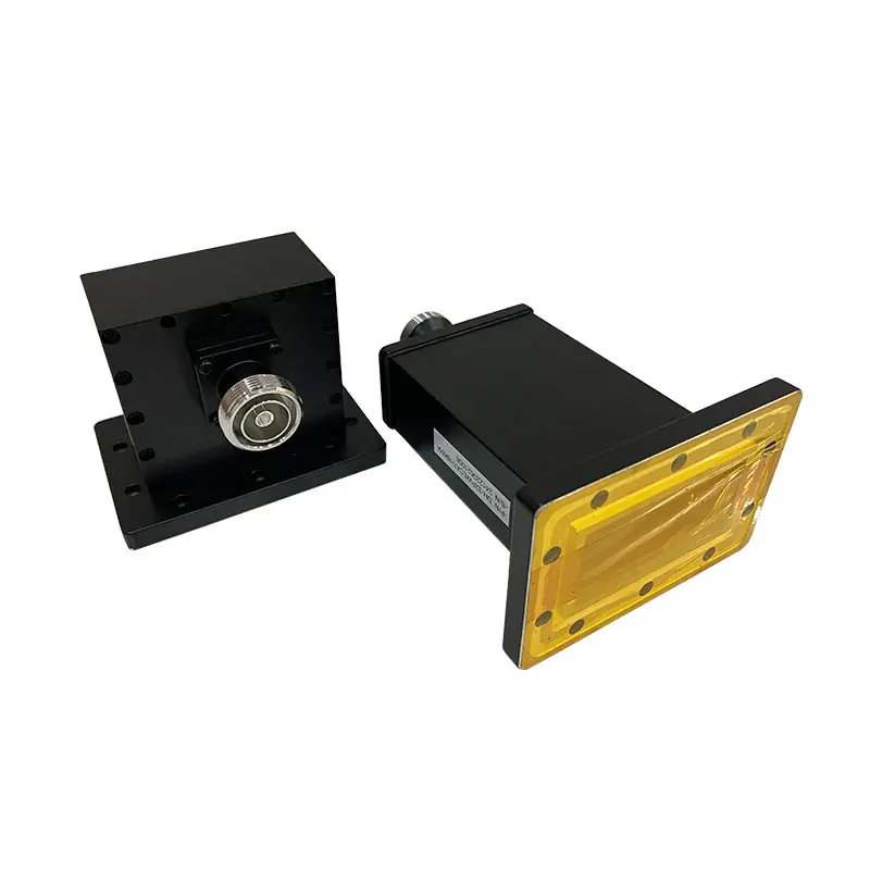
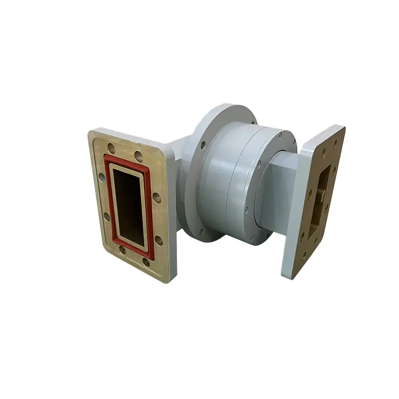
- Structural Robustness: Precision-machined from aluminum (or optional OFHC copper/brass), featuring symmetrical geometry for high mechanical strength, ease of integration, and resilience in harsh environments like radar rotary joints.
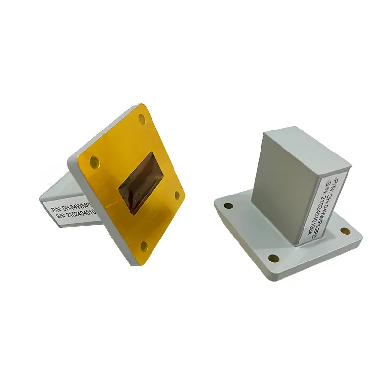
- Seamless Integration: Includes rectangular-to-circular transitions for hybrid waveguide systems, ensuring compatibility across standards (GB/EIA/153-IEC).
Applications
Deployed in critical infrastructure including radar systems (e.g., airborne/scannable arrays), satellite communication feeders, resonant cavities for frequency stabilization, and polarization attenuators in advanced telecom networks.
| MODEL | FREQUENCY TE11 (GHz) | STANDARD | VSWR Max. | WG PIPE SIZE | LENGTH (mm) | MATERIAL | DATASHEET | ||||
| GB | EIA | 153-IEC | I.D | THK. | |||||||
| DH-C40CW… | 3.89-5.33 | BY40 | WC205 | C40 | 1.03:1 | 51.99 | 2.54 | 50~3000 | Al | STEP | |
| DH-C48CW… | 4.45-6.23 | BY48 | WC175 | C48 | 1.03:1 | 44.45 | 2.54 | 50~3000 | Al | STEP | |
| DH-C56CW… | 5.30-7.27 | BY56 | WC150 | C56 | 1.03:1 | 38.1 | 2.03 | 50~3000 | Al | STEP | |
| DH-C65CW… | 6.21-8.51 | BY65 | WC128 | C65 | 1.03:1 | 32.537 | 2.03 | 50~3000 | Al | STEP | |
| DH-C76CW… | 7.27-9.97 | BY76 | WC109 | C76 | 1.03:1 | 27.788 | 1.65 | 50~3000 | Al | STEP | |
| DH-C89CW… | 8.49-11.6 | BY89 | WC94 | C89 | 1.03:1 | 23.825 | 1.65 | 50~3000 | Al | STEP | |
| DH-C104CW… | 9.97-13.7 | BY104 | WC80 | C104 | 1.03:1 | 20.244 | 1.27 | 50~3000 | Al | STEP | |
| DH-C120CW… | 11.6-15.9 | BY120 | WC69 | C120 | 1.03:1 | 17.415 | 1.27 | 50~3000 | Al | STEP | |
| DH-C140CW… | 13.4-18.4 | BY140 | WC59 | C140 | 1.03:1 | 15.088 | 1.015 | 50~3000 | Al | STEP | |
| DH-C165CW… | 15.9-21.8 | BY165 | WC50 | C165 | 1.03:1 | 12.7 | 1.015 | 50~3000 | Al | STEP | |
| DH-C190CW… | 18.2-24.9 | BY190 | WC44 | C190 | 1.03:1 | 11.125 | 1.015 | 50~3000 | Al | STEP | |
| DH-C220CW… | 21.2-29.1 | BY220 | WC38 | C220 | 1.03:1 | 9.525 | 0.76 | 50~3000 | Al | STEP | |
| DH-C255CW… | 24.3-33.2 | BY255 | WC33 | C255 | 1.03:1 | 8.331 | 0.76 | 50~3000 | Al | STEP | |
| DH-C290CW… | 28.3-38.8 | BY290 | WC28 | C290 | 1.03:1 | 7.137 | 0.76 | 50~3000 | Al | STEP | |
| DH-C330CW… | 31.8-43.0 | BY330 | WC25 | C330 | 1.03:1 | 6.35 | 0.51 | 50~3000 | Al | STEP | |
| DH-C380CW… | 36.4-49.8 | BY380 | WC22 | C380 | 1.03:1 | 5.536 | 0.51 | 50~3000 | Al | STEP | |
| DH-C430CW… | 42.4-58.1 | BY430 | WC19 | C430 | 1.03:1 | 4.775 | 0.51 | 50~3000 | Al | STEP | |
| DH-C496CW… | 46.3-63.5 | BY495 | WC17 | C496 | 1.03:1 | 4.369 | 0.51 | 50~3000 | Al | STEP | |
| DH-C580CW… | 56.6-77.5 | BY580 | WC14 | C580 | 1.03:1 | 3.581 | 0.51 | 50~3000 | Al | STEP | |
| DH-C660CW… | 63.5-87.2 | BY660 | WC13 | C660 | 1.03:1 | 3.175 | 0.38 | 50~3000 | Al | STEP | |
| DH-C765CW… | 72.7-99.7 | BY765 | WC11 | C765 | 1.03:1 | 2.769 | 0.38 | 50~3000 | Al | STEP | |
| DH-C890CW… | 84.4-116.0 | BY890 | WC9 | C890 | 1.03:1 | 2.388 | 0.38 | 50~3000 | Al | STEP | |
| Part Number Guide: DH-C104CW100A "C104"—Waveguide Size | WC59 "CW"—Waveguide Type | Circular Waveguide Raw Tubes "100"— Length | 100 mm "A/C"— Material | Aluminium, Cu |
|||||||||||
| Note: Raw Waveguide in most alloys including Aluminum, OFHC, Copper, Brass, and more. Standard waveguide lengths are 2000mm. and we can cut waveguide to your dimensions on request. |
|||||||||||