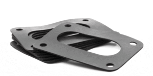
Waveguide conductive gaskets typically use silicone rubber filled with silver or nickel particles, with a standard thickness of about 0.69mm, capable of providing shielding effectiveness exceeding 100dB.
When selecting, choose O-type or D-type cross-sections based on WR flange dimensions (e.g., WR28); for high-pressure environments, metal skeleton reinforced types are recommended to prevent cold flow.
The unit price for standard types is around tens of RMB, and installation requires cleaning the flange surface and precisely controlling compression to ensure airtightness.
Table of Contents
Structure
For Cover/Flat Flanges (grooveless), 0.027″ (0.69mm) or 0.032″ (0.81mm) thick Die-Cut planar gaskets must be selected, utilizing elastomers with 60-80 Shore A hardness to fill surface micro-gaps.
For Choke/CPR Flanges with sealing grooves, O-type or D-type cross-section Molded gaskets must be used. Compression should be controlled between 15%-25%, ensuring the Groove Fill rate is below 95% to reserve space for thermal expansion.
The internal microstructure typically employs a silicone matrix filled with 45μm silver-plated metal particles, or embeds Monel mesh to enhance Cold Flow resistance, ensuring RF continuity across the full WR-22 to WR-650 frequency band.
Physical Forms
Planar Gaskets Cut from Sheet Stock
This form is most commonly found in Cover Flange or Flat Contact flanges. They do not have any grooves to accommodate the rubber and rely entirely on bolt torque to press the two large flat surfaces of the flanges together.
- Hard Data on Thickness Selection
Standard stock sheets are typically 0.027″ (0.69mm) or 0.032″ (0.81mm). There is a reason for selecting this thickness:- Too Thin (<0.020″): Cannot fill the microscopic Surface Finish of the flange. If the flange surface roughness exceeds 63 RMS, a gasket that is too thin will cause high-frequency signal leakage through tiny gaps.
- Too Thick (>0.062″): In high-frequency bands (such as Ka-band, 26.5-40 GHz), this introduces significant Impedance Discontinuity, increasing Voltage Standing Wave Ratio (VSWR). Typically, 0.062″ (1.57mm) or 0.125″ (3.18mm) thick gaskets are only used on cast aluminum parts with extremely poor flatness tolerances (exceeding 0.005 in/in) to compensate for gaps.
- Die-Cutting Tolerances and Hole Deformation
Dimensional tolerances for Steel Rule Die cutting are usually controlled within ±0.010″ (0.25mm).
There is a detail to note here: Bolt Holes on planar gaskets must be slightly larger than the holes on the flange. Because rubber is an incompressible fluid, it undergoes Lateral Displacement when compressed. If the bolt hole fit is too tight, the bolt insertion will squeeze the rubber, causing the flange edges to arch (Bowing), creating gaps in the contact surface. It is usually recommended to reserve a clearance of 0.015″ (0.38mm) per side.
Molded O-Rings
For CPR (Contact Pressure Rectangular) flanges and Choke flanges, rectangular grooves are cut into the flange face. In this case, molded cross-section gaskets must be used.
- Contact Stress Mechanics
The advantage of an O-section is that its contact with the groove bottom starts as a Line Contact. When pressure is applied, the contact area increases with compression, following a Hertzian Contact distribution.- Standard cross-section diameters are typically 0.063″, 0.093″, 0.125″.
- An engineering hazard of O-rings is “Rolling”. When installed in rectangular grooves (especially waveguides with large aspect ratios, like WR-284), O-rings are prone to twisting inside the groove.
- Position of the Parting Line
Molded O-rings must control Parting Line Flash. The MIL-DTL-83528 standard requires flash to be no more than 0.003″ (0.08mm) and must not be located on the conductive contact surface.
Flat-Bottomed D-Sections
To solve the rolling problem of O-rings, the D-section was designed. Its bottom is flat, and the top is a semi-circle.
- Contact Area Comparison
At the same compression ratio (e.g., 20%), the D-section provides a contact width about 30% wider than an O-section.- Stability: The flat bottom uses friction to “grip” the groove floor, preventing rolling during installation.
- Directionality: Installation must ensure the flat side faces down. If installed upside down, with the flat side facing the mating flange, sealing may fail due to flange surface irregularities.
- Calculation for Non-Standard Size Filling
If you are not using a standard CPR flange but a custom groove, the D-section height design must follow:
H_gasket = D_groove / (1 – C%)
Where C% is the target compression (usually 0.15). The D-section width is usually designed to be 0.010″ to 0.020″ smaller than the groove width for easy insertion.
Material-Saving Picture Frame Splicing
For large waveguides (such as WR-650 or WR-975), making a full mold is too expensive, and cutting from a whole sheet is too wasteful (the cut-out center is all scrap).
- Vulcanized Joints
Extruded conductive rubber strips are cut into four segments and secondary vulcanization welding is performed at the corners using a mold.- Joint Strength: The tensile strength at the joint must reach more than 80% of the material body.
- Conductive Continuity: This is the biggest risk point of the splicing process. If the conductive particle distribution at the joint is uneven, it will become a window for RF leakage. High-spec applications usually require X-ray inspection of joints or individual resistance testing (requiring cross-joint resistance < 20 mΩ).
- Right Angles vs. Radii
Spliced frames are usually right-angled (90 degrees). However, if the groove is milled, the corners will have a cutter Radius. It must be confirmed whether the gasket corners will cause interference. If splicing O-rings, rubber volume will accumulate at the corners, leading to excessive local compression (potentially reaching over 40%), causing that point to break first over time.
Internal Reinforcement Structures
Embedding Metal Mesh in Rubber
Before the conductive rubber is vulcanized, one or more layers of woven metal mesh are inserted.
- Mesh Material Selection
The material of the metal mesh must be electrically compatible with the conductive particles in the rubber; otherwise, electrochemical corrosion will occur internally.- Monel Alloy (NiCu): Monel wire is extremely tough and has excellent corrosion resistance. It is typically used with Silver-plated Aluminum (Ag/Al) or Silver-plated Copper (Ag/Cu) rubber.
- Aluminum (Aluminum 5056): When used with Silver-plated Aluminum rubber and the application environment is extremely sensitive to electrochemical corrosion (such as salt fog environments), aluminum mesh is the first choice, although its mechanical strength is inferior to Monel.
- Tin-plated Copper-Clad Steel (Ferrous / Sn-Cu-Fe): Mainly used for low-frequency scenarios requiring magnetic field shielding (H-Field), utilizing the high permeability of steel to enhance low-frequency attenuation.
- Knitting Process Details
The mesh here is not “woven” like cloth with interlaced warp and weft, but is a Knitted structure.- Why Knitted? The knitted structure consists of countless Interlocking Loops. This structure allows the mesh to undergo three-dimensional deformation along with the rubber during the molding process, without restricting rubber flow like plain woven mesh, which could lead to Delamination.
- Wire Diameter Specifications: Typically uses 0.0035″ (0.09mm) to 0.0045″ (0.11mm) wire.
- Layer Configuration: For 0.062″ (1.57mm) thick gaskets, two layers of mesh are usually implanted; thinner 0.032″ gaskets use a single layer.
- Cold Flow Resistance Data
According to the ASTM D621 test standard, unreinforced conductive rubber under 1000 psi pressure may deform by as much as 10-15% after 24 hours. However, with the addition of 30 mesh (Openings per inch) Monel mesh, the deformation can be controlled within 2-5%.
Vertically Oriented Wires (Like Brush Bristles)
This involves inserting thousands of tiny metal wires vertically into a pure silicone sheet.
- Vertical Conduction Mechanism
These metal wires are arranged perpendicular to the flange surface like a brush.- Density Data: Standard density is typically 600 to 900 wires/sq. inch.
- Connectivity: Each metal wire is an independent conductive channel. Since they are solid metal (commonly Monel or Aluminum), their longitudinal resistance is almost zero.
- Piercing Oxidation Layers: This is its strongest feature. Where the flange surface is oxidized or has a passivation layer (Chromate Conversion Coating), particle-filled rubber may have poor contact, but the tips of oriented wires can directly Bite Through the insulating layer under high pressure, achieving metal-to-metal contact.
- EMP and High Current Tolerance
When subjected to Electromagnetic Pulse (EMP) or lightning induced currents, particle contact points may fail due to microscopic welding. Oriented wire structures can withstand extremely high transient current densities.- Test Data: Under 10kA pulse current impact, the impedance change rate of oriented wire structures is usually less than 5%, while particle-filled types may increase by 50% or more, or even open circuit.
- Waterproofing Shortcomings and Remedies
The interface between the metal wire and silicone is a microscopic channel, and moisture will seep in along the metal wire.- Solution: The middle section has metal wires for conduction, and the sides are pure silicone for sealing (Weather Seal). However, this increases the gasket width and is not suitable for miniature waveguides like WR-22.
Expanded Metal Reinforcement
For extremely harsh aviation fuel or hydraulic fluid environments, Fluorosilicone is typically used. But the physical Tear Strength of fluorosilicone is very low, only about 60% of ordinary silicone.
- Structure Description
In this case, a layer of Expanded Aluminum or Monel mesh is sandwiched in the middle of the rubber. Unlike knitted mesh, this is a diamond-shaped hole structure formed by slitting and stretching a thin metal sheet.- Mechanical Gain: This structure provides extremely high in-plane tensile strength. If your waveguide interface requires frequent disassembly (Maintenance Access), or the gasket needs to be dragged for positioning during installation, ordinary conductive rubber might be torn apart, while this reinforced material is almost impossible to tear.
The Trade-off Between Hardness and Flange Pressure
Adding reinforcement structures comes at the cost of the material becoming harder.
| Reinforcement Type | Hardness Increase (Shore A) | Recommended Closure Force | Applicable Flange Type |
|---|---|---|---|
| Pure Elastomer (No Reinforcement) | +0 (Baseline) | 50 – 100 psi | Thin-walled cast flanges, soft covers. |
| Mesh Reinforced | +5 ~ +10 | 125 – 200 psi | Standard rigid waveguide flanges. |
| Oriented Wire | N/A (Acts rigid) | 250 – 500 psi | Heavy-duty high-pressure flanges, requires high-torque bolts. |
Lateral Blow-Out Limits
In high-power microwave systems, the interior of the waveguide may be filled with pressurized gas (such as dry air or sulfur hexafluoride SF6) to prevent breakdown, with pressures reaching 30-60 psi.
- Failure Mode
Unreinforced rubber gaskets, under sustained internal air pressure, may bulge outwards like a balloon, eventually leading to a “Blow-Out”. - Skeleton Function
The friction coefficient generated between the internal metal mesh and the flange surface, along with the tensile strength of the mesh itself, firmly “anchors” the rubber to the flange face. For pressurized waveguide systems exceeding 15 psi, mesh reinforcement structures must be used, otherwise the maintenance cycle will be significantly shortened.
Composite Structures
Co-extruded Dual-Layer Design
Simply put, two different rubbers are extruded simultaneously in one cross-section, chemically bonding together during vulcanization to become a single unit.
- Clear Division of Labor (Inner/Outer)
- Inner Layer (Conductive Core): Typically occupies 60% – 70% of the section width. This part hugs the waveguide aperture, using high-conductivity filling materials like Ag/Al (Silver-plated Aluminum) or Ag/Cu (Silver-plated Copper) silicone.
- Outer Layer (Environmental Seal): Located on the periphery, usually requiring a width of at least 0.030″ (0.76mm) to be effective. This part is pure silicone or fluorosilicone, completely free of metal particles.
- Bond Strength
These two materials are not glued together but undergo Co-crosslinking at high temperatures during vulcanization.- Test Standard: According to ASTM D412 tensile testing, when this dual-color strip is pulled forcefully, the break point (Failure Mode) must occur in the material body, absolutely not at the bond line between the two colors.
Fluorosilicone Combinations for Special Fluids
If your equipment is installed near fighter jet landing gear, or is likely to contact hydraulic fluid, de-icing fluid, or aviation kerosene (JP-4, JP-8), the outer seal cannot use ordinary silicone.
- Swell Percentage Data
When ordinary silicone contacts jet fuel, its volume swell rate can be as high as 20% – 25%.- Solution: The outer layer must use Fluorosilicone (MIL-R-25988 Type II). Its swell rate under fuel immersion is usually controlled within 5%.
- Cost Trade-off: Fluorosilicone raw material prices are typically more than 5 times that of ordinary silicone.
Injection Molding on Metal Skeletons
For miniature waveguides like WR-28 (Ka-band), or scenarios requiring rapid installation on high-volume assembly lines, flimsy rubber rings are hard to handle. This is where “Metal + Rubber” composite structures are used.
- Structure Description
First, a rigid metal carrier is stamped from Aluminum Alloy (6061-T6) or Stainless Steel (300 Series), typically with a thickness between 0.020″ and 0.040″. Then, this metal plate is placed into an injection mold, and a ring of conductive rubber is directly injection molded at the seal groove location. - Mechanical Advantages
- Compression Stop: The metal carrier itself acts as a limiter. When bolts are tightened, the flange plate stops when it hits the metal carrier. The rubber compression is precisely locked by the thickness difference of the metal plate (e.g., metal plate 0.5mm, rubber protrusion 0.6mm, compression is fixed at 0.1mm), completely eliminating the risk of crushing the seal due to overtightening.
- Microwave Performance Consistency: Because the rubber position is fixed by the precision metal plate, tolerances can be controlled within ±0.002″ (0.05mm). This is crucial for high-frequency systems above 40GHz, as any tiny gasket Misalignment will cause impedance jumps.
Hard Requirements for Groove Dimensions
To use a dual-seal structure, the prerequisite is that the flange groove must be wide enough.
- Width Calculation
If your existing groove is designed for a single type of O-ring, it likely won’t fit a dual structure.- Minimum Width: The cross-section width of a dual extrusion structure typically needs to be at least 0.100″ (2.54mm). The conductive core needs at least 0.060″ width to guarantee current flow, the outer skin needs at least 0.030″ for sealing, plus 0.010″ for transition zone tolerance.
- Retrofit Risk: If it’s a standard WR-90 CPR flange, the groove width is fixed. Forcing a dual structure in might cause the outer insulating rubber to be squeezed into the waveguide aperture (Aperture encroachment), which will instantly burn out during high-power transmission.
Performance
Typically, plane wave shielding effectiveness is required to reach 100 dB – 125 dB within the 20 MHz – 10 GHz frequency band, and volume resistivity needs to be lower than 0.004 Ω·cm to ensure low insertion loss.
For outdoor applications, electrochemical compatibility is determined by the potential difference between the flange material and the gasket, which needs to be controlled within 0.25V (for aluminum flanges) to pass the 168-hour salt fog test (ASTM B117).
Regarding mechanical performance, the Compression Set should be less than 35% under a 100°C/72 hours test to maintain long-term airtightness (IP65/IP67) at the flange connection.
Shielding Effectiveness
Influence of Frequency on Shielding Data
In different frequency bands, the attenuation capability of gaskets shows significant differences.
- 20 MHz – 100 MHz (Magnetic Field Region)
In this low-frequency band, shielding mainly relies on the material’s Absorption Loss. Since the wavelength is extremely long (e.g., 20 MHz wavelength is about 15 meters), only materials with high magnetic permeability can provide effective attenuation.- Ordinary Conductive Rubber: Average performance. Since the silicone matrix itself is non-magnetic, attenuation relies mainly on the thickness of metal fillers.
- Typical Data: Silver-plated Aluminum (Ag/Al) typically provides 60 dB – 70 dB shielding in a 20 MHz H-field. To raise this above 80 dB, it is usually necessary to increase the gasket thickness or select fillers with higher permeability like Silver-plated Nickel (Ag/Ni).
- 100 MHz – 10 GHz (Plane Wave Region)
This is the operating band for most radar, avionics, and communication equipment. In this range, Reflection Loss dominates. The higher the surface conductivity of the material, the more energy is reflected back to the source, and the less energy penetrates.- Skin Effect: As frequency rises, current tends to flow on the gasket surface. As long as the conductive particles on the gasket surface are in tight contact, extremely high shielding values can be achieved.
- Typical Data: In 10 GHz plane wave tests, high-performance Silver-plated Copper (Ag/Cu) materials can easily reach 110 dB – 125 dB. Even lower-cost Nickel Graphite (Ni/C) can typically maintain around 100 dB.
- 10 GHz – 40 GHz+ (Microwave and Millimeter Wave)
Wavelength shortens to the millimeter level (40 GHz wavelength is about 7.5 mm). At this point, shielding effectiveness no longer depends solely on material conductivity but more on Physical Gaps.- Gap Leakage: If the flange face is uneven or compression force is insufficient, creating a tiny gap 3mm long, it can become an effective slot antenna at 40 GHz, causing electromagnetic waves to pass directly through, potentially dropping shielding effectiveness from 100 dB to below 60 dB instantly.
- Countermeasures: High-frequency applications must use smaller particle size fillers (e.g., 30-45 microns) to ensure there are no voids at the microscopic interface.
Specific Performance of Different Metal Fillers
MIL-DTL-83528 classifies different polymer and metal filler combinations into different “Types”.
| Filler Type | MIL-DTL-83528 Type | 200 MHz (E-Field) | 10 GHz (Plane Wave) | Performance Characteristics |
|---|---|---|---|---|
| Silver-plated Copper (Ag/Cu) | Type A / C / K | > 120 dB | > 115 dB | Highest conductivity, mainly used for top-tier military shielding, capable of blocking EMP pulses. |
| Silver-plated Aluminum (Ag/Al) | Type B / D | > 110 dB | > 105 dB | Low density (approx 2.0 g/cc), 50% lighter than Ag/Cu, suitable for weight-sensitive aerospace equipment. |
| Silver-plated Nickel (Ag/Ni) | Type E | > 100 dB | > 100 dB | Balanced performance in high frequencies and low-frequency magnetic fields; the nickel core under the silver plating offers a good corrosion-resistant base. |
| Nickel Graphite (Ni/C) | Type L | > 80 dB | > 90 dB | First choice for commercial grade. Although data at 10GHz is 20dB lower than silver-based series, it meets most FCC/CE civilian standards. |
| Pure Silver (Pure Ag) | Type M | > 120 dB | > 120 dB | Extremely expensive, only used for medical equipment or extreme instrumentation, possessing the best antibacterial and conductive properties. |
How Compression Changes Shielding Values
Shielding effectiveness on datasheets is usually measured under ideal laboratory conditions—meaning highly polished, gold-plated flange surfaces with immense pressure applied.
- Contact Resistance
Shielding effectiveness is inversely proportional to the contact resistance at the flange-gasket interface.- Low Compression (5% – 10%): Conductive particles fail to fully pierce the oxidation layer or passivation film on the flange surface. Contact resistance can be as high as 0.100 Ω, at which point shielding effectiveness may be 10 dB – 15 dB lower than the nominal value.
- Standard Compression (15% – 25%): This is the optimal working zone. The silicone matrix deforms, forcing internal metal particles to squeeze against each other and press tightly against the flange surface. Contact resistance drops to 0.002 Ω – 0.005 Ω, and shielding effectiveness reaches its peak.
- Over-Compression (> 30%): Although contact resistance might decrease further, the silicone structure may rupture, and resilience is lost. Once disassembled or subjected to thermal cycling, shielding effectiveness will permanently drop.
Data Decay After Environmental Aging
Shielding value retention after ASTM B117 salt fog testing and heat aging tests is the watershed distinguishing “military grade” from “consumer grade” products.
- Salt Fog Corrosion Impact
When salt fog penetrates the flange interface, metal fillers undergo oxidation or electrochemical corrosion.- Ag/Cu Material: If edge sealing is not added, after 48 hours of salt fog testing on aluminum flanges, contact resistance increases 100-fold, and shielding effectiveness may drop by 20 dB – 40 dB.
- Ni/C Material: Since graphite and nickel are extremely stable, after 1000 hours of salt fog testing, the drop in shielding effectiveness is typically less than 5 dB.
- Heat Aging Impact
After operating continuously at 125°C for 1000 hours, the substrate may harden. If hardness rises from Shore A 65 to Shore A 80, compression resilience becomes insufficient. In vibration environments, the flange surface may experience transient Micro-separation, leading to intermittent fluctuations in shielding effectiveness of 3 dB – 10 dB.
Electrochemical Compatibility
How to Interpret that 0.25V Red Line
In the MIL-STD-889 standard, all metals are arranged in an “Electrochemical Series”.
The most intuitive way to assess compatibility is subtraction: calculate the potential difference between two metals.
The harsher the environment, the smaller the allowed potential difference:
- Controlled Environment (Indoor/Dry): Max potential difference 0.50 V allowed. Even with some potential difference, without moisture as an electrolyte, corrosion reactions are very slow.
- Harsh Environment (Outdoor/Salt Fog/Shipboard): Max potential difference 0.25 V allowed. Once this number is exceeded, obvious white or green corrosion products will be seen within days in a salt fog environment.
To avoid looking up complex chemical tables, here are typical potential values relative to a Saturated Calomel Electrode (SCE) for common materials (approximate values):
| Material Type | Typical Potential Value (Volts) | Attributes |
|---|---|---|
| Silver Plate | -0.15 V | Most inert (Cathodic), least likely to rot, but accelerates corrosion of others |
| Nickel | -0.25 V | Relatively inert |
| Copper | -0.35 V | Relatively inert |
| Graphite | +0.20 V to -0.05 V | Very stable, potential heavily influenced by process |
| Aluminum 6061-T6 | -0.75 V | Prone to corrosion (Anodic) |
| Magnesium Alloy | -1.60 V | Extremely active, corrodes very easily |
Do the Math:
If you press a Silver-plated Copper (Ag/Cu, -0.15V) gasket against an Aluminum 6061 (-0.75V) flange:
(-0.15) – (-0.75) = 0.60 V
This value far exceeds the 0.25V red line.
Aluminum Flanges are the Biggest Victims
To save weight in aerospace and radar systems, 90% of waveguide flanges are aluminum alloys (6061-T6 or 6063-T4).
Aluminum is extremely active; the reason it doesn’t rot ordinarily is due to a natural oxide film on its surface, but this film is non-conductive.
For RF conductivity, we must polish off this film or apply a conductive Chromate Conversion Coating (like Alodine 1200 or MIL-DTL-5541 Type II).
This exposes “bare” aluminum directly to the conductive gasket. At this point, the metal filler in the gasket determines the fate of the aluminum flange:
- Ag/Al (Silver-plated Aluminum) is a Sibling
This is the safest combination. Since the core of the filler is also aluminum, although the outer silver layer has a higher potential, the overall composite material’s electrochemical activity is tuned to be very close to the aluminum flange.- Data Performance: In ASTM B117 salt fog tests, Ag/Al gaskets paired with aluminum flanges can typically last 168 hours or even 504 hours, with contact resistance change rates less than 20%.
- Ag/Cu (Silver-plated Copper) is a Wrecking Crew
As calculated before, a 0.60V potential difference is a disaster. Testing this combination in a salt fog chamber, opening it after 48 hours reveals the flange contact surface covered in white aluminum oxide powder (Pitting Corrosion), with pits even as deep as 0.5mm.- Consequences: Contact resistance skyrockets from an initial 2 mΩ to over 1000 mΩ (1Ω), and shielding effectiveness instantly drops by 40 dB – 60 dB.
Nickel Graphite (Ni/C) – The Value Choice
Although Nickel Graphite filler’s conductivity (volume resistivity approx 0.05 Ω·cm) is not as good as silver-plated materials (0.002 Ω·cm), it is extremely “diplomatic” electrochemically.
- High Tolerance
Nickel’s potential (approx -0.25V) is between silver and copper, and graphite is very stable. When contacting aluminum flanges, the potential difference is about 0.50V. Although it looks larger than 0.25V, because the electrochemical reaction rate (polarization effect) on the graphite particle surface is extremely slow, the actual corrosion speed is far lower than the theoretical calculation. - Actual Testing
In aluminum chassis applications for commercial communication base stations (like 5G RF units), Ni/C gaskets after 1000 hours of salt fog testing show that while the aluminum surface discolors, it does not produce the thick corrosion layer that pushes the gasket away, and sealing performance remains IP67.
Real Data in Salt Fog Tests
ASTM B117 is the most universal standard (5% NaCl solution, 35°C spray).
Pass/Fail is usually judged on two dimensions:
- Physical Appearance (Visual):
Has corrosion product spread beyond the seal width?- Strict Standard: Corrosion products must not penetrate 1/3 of the seal depth.
- Resistance Jump (Electrical Stability):
This is what RF engineers care about most. Some materials look fine but resistance has increased.- Excellent: Resistance increase after test < 15 mΩ (milliohms).
- Pass: Resistance increase after test < 50 mΩ.
- Fail: Resistance doubles or opens after test.
Typical Aging Data Comparison (Paired with 6061-T6 Aluminum Plate, 168 Hours Salt Fog):
| Gasket Material | Initial Flange Contact Resistance | Contact Resistance After Salt Fog | Status Description |
|---|---|---|---|
| Ag/Al (MIL-DTL-83528 Type B) | 1.5 mΩ | 1.8 mΩ | Almost no change, perfect electrical stability. |
| Ni/C (Commercial Grade) | 20.0 mΩ | 25.0 mΩ | Base resistance slightly higher, but very stable. |
| Ag/Cu (MIL-DTL-83528 Type A) | 1.2 mΩ | > 500 mΩ | Complete failure, producing massive white oxide insulation layer. |
| Ag/Glass (Type M) | 3.0 mΩ | 4.5 mΩ | Performance passable, as glass beads don’t react, relying only on the silver layer. |
How to Save It If You Must Mix and Match
Some high-performance radars must use Ag/Cu gaskets to resist EMP, but the flanges are aluminum. How to prevent corrosion?
- Dual Seal Design (Dual Seal / Co-extrusion)
This is the safest method. Make the conductive gasket a “Conductive Inner, Insulating Outer” structure.- Inner: Conductive rubber responsible for RF shielding.
- Outer: Vulcanized pure silicone ring.
- Principle: Pure silicone blocks salt fog and moisture outside; the internal conductive part stays in a dry environment, so the electrochemical reaction stops naturally. This design allows the Ag/Cu + Aluminum flange combination to easily pass 500 hours of salt fog testing.
- Flange Surface Treatment (Plating)
If you don’t change the gasket, change the flange surface.- Tin Plate: Tin’s potential is about -0.65V, very close to aluminum and acceptable with silver. It acts as a good buffer layer.
- Electroless Nickel: Plating a layer of nickel on the aluminum flange raises the flange potential to about -0.25V, narrowing the gap with Ag/Cu and significantly reducing corrosion risk. Note that the plating must be thick enough (usually > 25 microns), otherwise pinholes will accelerate local pitting.
Compression Characteristics
How Much Compression is Just Right
Every conductive rubber has its strict “Force-Deflection” curve. For most Flat Gaskets or Molded waveguide gaskets, the optimal working range is 15% to 20% of the original thickness.
- Danger Zone (< 10%):
This is the “Under-compression” state. Conductive particles are not squeezed enough to pierce the natural oxidation layer of the aluminum flange.- Consequences: Contact resistance can be as high as 100 mΩ or more. Under high-frequency vibration, micro-bouncing occurs at the interface, raising the system noise floor.
- Safety Zone (15% – 25%):
This is the “Sweet Spot”. The silicone matrix undergoes elastic deformation, filling the microscopic roughness of the flange surface (typically 63-125 RMS finish).- Data: At this point, airtightness reaches IP67, and shielding effectiveness is at its peak (>100 dB).
- Destruction Zone (> 30%):
This is “Over-compression”. Metal filler particles are squeezed until they lock together, and silicone chains are over-stretched or even broken.- Consequences: The material enters the plastic deformation stage and permanently loses resilience. Once you need to disassemble the flange for maintenance, the gasket is ruined and must be replaced.
Tip: For common 0.020 inch (0.5 mm) or 0.032 inch (0.8 mm) thick waveguide gaskets, 15% compression means you only have 0.075 mm to 0.12 mm of travel space. This usually requires using a Torque Wrench combined with hard stop designs.
How Much Force to Press Down
This depends on the material’s Hardness (Durometer, Shore A) and Load Deflection.
Different fillers have huge hardness differences, directly determining bolt torque requirements:
| Material Type | Hardness (Shore A) | Pressure for 10% Compression (PSI) | Applicable Flange Type |
|---|---|---|---|
| Pure Silicone (No Filler) | 30 – 50 | 25 – 50 PSI | Plastic or thin-walled metal housings |
| Ag/Al (Type B) | 65 ± 5 | 150 – 200 PSI | Standard aluminum cast waveguides |
| Ni/C (Type L) | 75 ± 5 | 200 – 300 PSI | Thicker stainless steel or aluminum flanges |
| Ag/Cu (Type A) | 85 ± 5 | > 400 PSI | Military heavy-duty flanges, requires high-strength bolts |
Will It Bounce Back After Baking?
This is the cruelest indicator for assessing Life Span. Compression Set describes how much thickness “doesn’t come back” after the material is relieved of pressure.
Testing usually follows ASTM D395 Method B: Compress the sample by 25%, bake in a 100°C oven for 72 hours, then measure thickness loss after cooling.
- Why Metal Fillers are a Burden:
Pure silicone has extremely low compression set (< 5%), like a spring. But waveguide gaskets are filled with 70% – 80% by weight metal powder, and these metals have no elasticity.- Ag/Al (Silver-plated Aluminum): Performs best. Since particles are light and regular in shape, its compression set is typically controlled at 15% – 25%.
- Ag/Cu (Silver-plated Copper): Performs poorly. Since copper particles are heavy and hard, impeding silicone rebound, its set rate is often as high as 30% – 50%.
- Ag/Glass (Silver-plated Glass): Since glass beads are rigid spheres, some formulations can have set rates as low as 10% – 15%.
- Failure Threshold:
When compression set exceeds 50%, once the equipment undergoes severe thermal cycling (e.g., dropping from +85°C to -40°C), thermal contraction of the material plus lost rebound force will cause interface pressure to instantly drop to zero, leading to a Cold Leak.
Don’t Let Flange Unevenness Ruin Everything
Lab data is measured on precision-ground steel plates, but real-world waveguide flanges are often rough.
- Flange Flatness:
For millimeter-wave applications (like over 40 GHz), flange flatness tolerance is usually required to be within 0.001 inch (0.025 mm). If flange warpage exceeds 0.005 inches, a thin waveguide gasket (usually only 0.5 mm thick) simply cannot compensate for this gap through local deformation. - Tolerance Stack-up Analysis:
The thickness tolerance of conductive rubber sheets is typically ±0.005 inches (0.13 mm).- Worst Case: If you get a gasket on the thin side (-0.005″) and encounter a slightly recessed flange groove (+0.003″), actual compression might drop below 5%, causing total electromagnetic shielding failure.
- Strategy: When designing groove depth, calculate compression rates based on the gasket’s Least Material Condition (LMC); it is better to compress slightly tighter than to have no contact.
When to Use Mechanical Stops
To prevent operators from crushing the gasket due to shaky hands, Mechanical Stops are the safest design.
- Groove Design:
This is the most common stop method. Place the gasket in a milled slot on the flange.- Depth Calculation: Groove Depth = Gasket Max Thickness × (1 – Target Compression %).
- Volume Fill: Never fill it completely. Silicone is virtually incompressible (constant volume). When flattened, it must expand sideways. Groove Width must leave enough space to ensure the fill rate does not exceed 90%. If filled to 100%, immense hydraulic pressure will crack the flange edges.
- Compression Stops:
If using die-cut gaskets on flat flanges, metal limit pillars can be embedded in the gasket, or spacers can be used at bolt locations to forcibly lock the final height, eliminating human torque errors.
Price
The unit price of waveguide conductive gaskets varies greatly, typically ranging from $2 (Commercial Grade) to $150+ (Space Grade).
Raw materials are the primary variable affecting cost. The prices of filler materials like Pure Silver (Ag) and Silver-plated Copper (Ag/Cu) are directly linked to the international precious metals market, and their cost is typically 5-10 times that of Nickel Graphite (Ni/C).
Manufacturing processes also determine cost structure: Molded processes usually require an NRE (Non-Recurring Engineering) mold fee of $1,500–$5,000, but for volumes exceeding 1,000 units, the per-unit cost can be reduced by 40-60% compared to Die-cut.
Additionally, batch testing requirements compliant with MIL-DTL-83528 or ASTM E595 (Low Outgassing) standards will significantly increase the final delivery price.
Conductive Fillers
Silver-plated Aluminum (Ag/Al)
Currently, in defense and avionics sectors, MIL-DTL-83528 Type B (Silicone) and Type D (Fluorosilicone) are the most widely applied standards.
- Technical Specs:
- Volume Resistivity: Typical value is 0.008 Ω-cm. Although slightly higher than silver-plated copper, it is sufficient to provide 100 dB plane wave shielding effectiveness at 10 GHz.
- Specific Gravity: About 2.0 – 2.2 g/cc. Compared to copper-based materials, it can reduce gasket weight by 40% for airborne equipment.
- Electrochemical Properties: This is the biggest premium point for Ag/Al. Since the core is aluminum, the potential difference is minimal when paired with common 6061-T6 or 7075 aluminum alloy flanges.
- Reliability Data:
In ASTM B117 salt fog tests, Ag/Al gaskets paired with aluminum flanges can typically pass 168 hours or even 504 hours of neutral salt fog testing, with contact resistance change rates typically keeping < 20%. - Cost Logic:
Although the aluminum substrate is cheap, the silver plating process is complex. Its price is usually in the mid-to-high range (Relative Index 5.0). However, over the full life cycle, because it saves the extra steps of special plating (like nickel or tin plating) on flanges for corrosion protection, the total system cost is often lower.
Silver-plated Copper (Ag/Cu)
Before the 1990s, this was the standard configuration for high-performance gaskets (corresponding to MIL-DTL-83528 Type A, C, K).
- Technical Specs:
- Volume Resistivity: Extremely low, typically < 0.004 Ω-cm. This low resistivity gives it excellent EMP (Electromagnetic Pulse) handling capability, able to withstand momentary large current shocks (> 10 kA/m).
- Shielding Effectiveness: Easily exceeds 110 dB at 18 GHz.
- Specific Gravity: The downside is obvious, reaching as high as 3.5 – 4.0 g/cc.
- Usage Risk:
Electrochemical corrosion is the biggest hazard. Silver and copper are both noble metals, creating a strong galvanic cell effect when contacting aluminum flanges. In humid environments, the aluminum flange acts as a sacrificial anode and corrodes rapidly, leading to seal failure. Unless the flange surface is also silver or nickel plated, using Ag/Cu outdoors is not recommended. - Cost Logic:
Price is influenced by both copper and silver market fluctuations, Relative Index 6.0 – 8.0. Typically only used in ground radar stations or bunkers with hard indicators for EMP protection.
Silver-plated Glass (Ag/Glass)
When satellites or drones count every gram of payload weight, Ag/Glass (corresponding to MIL-DTL-83528 Type M) is the only choice.
- Technical Specs:
- Specific Gravity: Lowest in the industry, only 1.9 – 2.0 g/cc.
- Volume Resistivity: 0.010 – 0.020 Ω-cm. Since the glass core is non-conductive, current relies entirely on the surface silver layer, so conductivity is weaker than all-metal particles.
- Shielding Effectiveness: Average 90 – 100 dB.
- Process Limits:
Glass beads will crush under excessive compression. Typically recommended compression is 10% – 15%, strictly forbidden to exceed 20%, otherwise conductive paths break and performance falls off a cliff. This requires very precise flange machining tolerances. - Cost Logic:
Although the glass substrate is extremely cheap, manufacturing yield is low to ensure plating uniformity and bead integrity. Its unit price is not cheap, Relative Index 4.0 – 5.0.
Nickel Graphite (Ni/C)
If you take apart a base station filter or enterprise router, you will likely see black-grey Ni/C gaskets.
- Technical Specs:
- Volume Resistivity: 0.050 – 0.100 Ω-cm. While an order of magnitude higher than silver-based materials, it is more than sufficient for 60 – 80 dB shielding effectiveness required by FCC or CE standards.
- Broadband Response: In high-frequency bands (> 40 GHz), due to nickel’s magnetic permeability, skin depth decreases, and its shielding effectiveness drops faster than silver-based materials.
- Flame Retardancy: Commercial grade Ni/C is usually paired with UL 94 V-0 flame retardant silicone, a mandatory requirement for consumer electronics.
- Cost Logic:
Nickel prices are far lower than silver and fluctuate less. Its raw material cost is typically only 1/5 or less of Ag/Al. In large-scale procurement for consumer electronics (millions of units), this is the only solution that can push unit costs below $0.50.
Pure Silver (Ag)
Only used for special medical equipment or extremely high-sensitivity receivers.
- Technical Specs:
- Volume Resistivity: < 0.002 Ω-cm.
- Non-Magnetic: Pure silver is non-magnetic, suitable for environments sensitive to magnetism like MRI (Magnetic Resonance Imaging).
- Cost Logic:
Relative Index 10.0+. Prices float in real-time with the LME (London Metal Exchange) silver price, and supplier quotes are typically valid for only 24-48 hours.
Manufacturing Processes
Compression Molding
This is the standard process for producing high-precision, complex cross-section (e.g., O-Shape, D-Shape, P-Shape) waveguide gaskets.
- Process Principle:
Uncured conductive rubber compound is placed into a heated steel mold, subjected to 5-10 tons of pressure, and vulcanized at 150°C – 170°C. - Applicable Scenarios:
- Volume > 1,000 units/year.
- Requires 3D structures (e.g., with locating pins, mounting holes, or non-planar structures).
- Extremely high dimensional tolerance requirements (meeting RMA A2 Precision class).
- Cost Accounting:
- Upfront Investment (NRE): High. A multi-cavity tool typically costs between $2,000 – $6,000. Mold life is usually 100,000 shots.
- Unit Cost: Very low. Since material waste is minimal (only a small amount of flash), and multiple parts are formed at once, when volume reaches 5,000 units, the unit price is usually only 1/2 of die-cut parts.
- Technical Pitfalls:
- Parting Line: A tiny raised line remains where the mold halves close. According to MIL-DTL-83528, parting line mismatch must not exceed 0.13mm (0.005″), and flash thickness must be < 0.08mm, otherwise flange sealing will be compromised.
- Shrinkage: Conductive rubber shrinks 2% – 4% after cooling. If the mold design does not compensate for this ratio, the final product dimensions will be undersized.
Die-Cutting
If your waveguide flange is planar (Flat Flange) and only needs simple rectangular or square gaskets, die-cutting is the fastest choice.
- Process Principle:
Using a Steel Rule Die to punch and cut pre-cured conductive rubber Sheet Stock. - Applicable Scenarios:
- Volume < 500 units or Prototyping stage.
- Planar gaskets, thickness typically between 0.5mm (0.020″) and 3.2mm (0.125″).
- Cost Accounting:
- Upfront Investment: Extremely low. Simple laser dies cost only $150 – $300. Lead time is usually just 2-3 days.
- Unit Cost: Higher. The main reason is low Material Yield. For expensive Ag/Al materials, scrap waste after punching can be as high as 40%, and this scrap cannot be recycled, so the cost is fully factored into the unit price.
- Technical Limitations:
- Section Limits: Can only cut rectangular cross-sections. Cannot make O-rings (because O-ring cross-sections are circular, while sheet cuts are square-edged).
- Concavity Effect: For soft materials thicker than 2.0mm, punched edges will concave, resulting in an actual contact area smaller than the design area, potentially affecting high-frequency shielding effectiveness.
Extrusion and Splicing
When waveguide dimensions are very large (e.g., large radar antenna arrays with perimeters over 600mm), or only a few meters of sealing strip are needed, opening a mold is not cost-effective, and die-cut sheet sizes aren’t big enough.
- Process Principle:
Conductive rubber is continuously extruded and cured into lines through a specifically shaped Die. Then it is cut to the required length and joined into a closed loop via Hot Splicing or Cold Bonding. - Applicable Scenarios:
- Super large size gaskets (ID > 200mm).
- Groove Mount.
- Cost Accounting:
- Upfront Investment: Low. Extrusion dies are typically <$500.
- Unit Cost: Medium. Priced by the meter, but each Splice requires an additional $1.00 – $3.00 labor processing fee.
- Performance Data:
- Joint Strength: High-quality hot vulcanized joints should have a Tensile Strength reaching 50% – 70% of the material body. If it breaks at the joint when pulled, the process is substandard; a qualified break point should occur in the material body.
- Hardness Unevenness: Hardness at the joint is usually 5 – 10 Shore A higher than the body, which may cause the joint to become a leak point under low compression force.
Automated Dispensing (FIP)
This is a completely different approach: instead of producing independent gaskets, conductive adhesive is directly “drawn” onto the metal chassis.
- Process Principle:
Using a 3-axis or 4-axis CNC robot, paste-like conductive silicone is directly dispensed into the waveguide flange or chassis labyrinth groove, followed by high-temperature curing. - Applicable Scenarios:
- Cell phone base station filters, millimeter-wave radar modules.
- Microwave components with extremely small space where manual installation of traditional gaskets is impossible.
- Extremely narrow flange widths (< 1.0mm).
- Data Comparison:
- Shielding Effectiveness: Typically 10 – 20 dB lower than traditional molded gaskets. To facilitate dispensing, FIP materials have lower filler content, with volume resistivity typically around 0.010 Ω-cm.
- Compression Force: FIP gaskets are very soft, with hardness typically 40 – 50 Shore A, requiring very little compression force, suitable for thin-walled die-cast aluminum housings.
- Cost Logic:
No mold fee, but high equipment depreciation and programming costs. Unit price depends on Bead Length and dispensing time. Once a defect occurs, it often requires scrapping the expensive metal housing together with it, or undergoing complex chemical rework cleaning.
Waterjet Cutting
For prototyping orders with large thickness where you don’t want to make a die.
- Process Principle:
Cutting sheets using a 60,000 PSI high-pressure water stream mixed with Garnet abrasive. - Advantages:
- No Heat Affected Zone (No HAZ): Unlike laser cutting which burns conductive particles (causing non-conductive edges), waterjet cutting is a cold process, preserving edge conductivity.
- Zero Mold Fee: Direct processing from DXF files.
- Precision Limits:
Waterjets have a Kerf width of 0.1mm – 0.2mm, and the cut surface will show a slight “V” shape Taper. Controlling dimensions for narrow gaskets less than 2mm wide is difficult.
Price Differences
The Logic of Quantity and Setup Fees
Waveguide gasket production is a process with high fixed costs and low variable costs.
- Minimum Lot Charge (MLC):
Most US and European conductive rubber manufacturers have a hard “Startup Fee” or “Minimum Order Value (MOV)”, typically between $250 – $500.- Scenario Deduction:
Suppose you need 5 custom Ag/Al gaskets, and material cost is only $5/ea.- Supplier calculation: (MOV $300) / 5 units = $60/unit.
- If you buy 100 units: (MOV $300 + 100*$5) / 100 units = $8/unit.
- Data Inflection Point:
The price curve typically flattens out at 500 – 1,000 units. Below this magnitude, most of what you pay is machine Setup Time and administrative costs, not the product itself.
- Scenario Deduction:
Test Reports Are More Expensive Than the Product
In the aerospace field, a piece of paper (test report) often costs more than a box of parts.
| Document/Test Type | Content Included | Typical Cost (USD) | Price Impact |
|---|---|---|---|
| Standard CoC (C of C) | Only declares compliance with order requirements, no specific data. | $0 (Usually included) | None |
| Test Data Report | Provides specific values for hardness, specific gravity, resistivity of the batch. | $50 – $150 | Charged per occurrence |
| Slab Testing | Curing a test slab specifically for this order for destructive tensile testing. | $300 – $500 | Significantly increases small order cost |
| Group B Qualification | Full set of aging, salt fog, EMP tests per MIL-DTL-83528. | $3,000 – $8,000 | Extremely high, usually only for major projects |
- Strategy to Avoid Pitfalls:
Unless mandated by contract, do not note “Group A Test Data Required” on the PO (Purchase Order). For commercial applications, asking for a free Standard CoC is legally sufficient.
The Tighter the Tolerance, the steeper the Price
The tolerance class casually selected by design engineers in the drawing title block directly determines the factory Scrap Rate.
- RMA A3 (Commercial) vs. RMA A2 (Precision):
- For a die-cut gasket with thickness 1.57mm (0.062″):
- RMA A3 allows tolerance ±0.20mm. The factory can use standard steel rule dies, yield nearing 98%.
- RMA A2 requires tolerance ±0.10mm. This exceeds the control range of rubber material under natural rebound. The factory must perform 100% Inspection and may reject 15% – 20% of parts with edge dimensional deviations.
- Cost Multiplier:
Once RMA A2 or tighter tolerance is marked on the drawing, suppliers typically multiply the base quote by a factor of 1.3 – 1.5 to cover potential scrap risk.
- For a die-cut gasket with thickness 1.57mm (0.062″):
Precious Metal Surcharge
Since Ag/Al, Ag/Cu, and Pure Silver gaskets contain a high percentage of silver (typically > 60% by weight), their price is pegged to the International Silver Price (Silver Fix).
- Base Price Mechanism:
Supplier annual quotes are usually based on a set silver price baseline (e.g., Silver @ $25.00/oz). - Fluctuation Algorithm:
When LME (London Metal Exchange) or COMEX silver prices rise, suppliers levy a surcharge.- Calculation Formula: Surcharge = (Current Silver Price – Base Silver Price) × Product Silver Content Factor.
- Actual Impact: If silver price rises from $25 to $35/oz, the unit price of a large waveguide gasket may rise by $2 – $5.
- Quote Validity:
Quotes for silver-containing products typically have short validity, only 7 – 14 days. During periods of extreme market volatility (like 2020-2021), some suppliers even provide spot prices valid for only 24 hours.
Premium for Speed
Time is money, vividly demonstrated in the supply chain. The production cycle for standard conductive rubber is typically 4 – 6 weeks. If you need to cut in line, it costs a fortune.
- Expedite Fee (Break-in Fee):
If you request delivery within 1 week, the factory needs to interrupt the existing production schedule and re-clean mixers and molds. This typically incurs an expedite premium of 25% – 50%, and usually has a minimum starting expedite fee of $500. - Stock vs. Custom:
- Buying stock standard M83528/004 gaskets has a fixed price.
- If you need to cut standard parts to a specific length, although there is no mold fee, it adds $1 – $2 in Labor Cost for cutting.
Hidden Packaging and Compliance Costs
Do not ignore those inconspicuous auxiliary requirements, they also accumulate costs.
- Individual Bagging:
If requiring each gasket to be bagged separately in anti-static bags with labels, labor costs will increase the unit price by $0.20 – $0.50. For Ni/C gaskets with already low unit prices, this could double the price. - PSA Backing (Pressure Sensitive Adhesive):
For ease of installation, engineers often request conductive adhesive backing.- Material Cost: 3M 9713 or 9719 conductive tapes are expensive themselves.
- Processing Cost: Applying adhesive increases die-cutting difficulty (adhesive sticks to the blade), slowing down processing. Typically, gaskets with PSA are 15% – 25% more expensive than those without.


