When designing or selecting an antenna, tracking six key parameters ensures optimal performance. The gain, typically ranging from 3 dBi to 20 dBi, determines directional efficiency, while the frequency range (e.g., 2.4 GHz–5 GHz for Wi-Fi) must match the application. VSWR (Voltage Standing Wave Ratio) below 2:1 indicates good impedance matching, minimizing signal loss. Radiation pattern (omnidirectional or directional) affects coverage, with beamwidth (e.g., 30°–90°) defining the signal spread. Polarization (linear or circular) must align with the transmitter/receiver. Finally, return loss (better than -10 dB) ensures minimal reflected power. Testing with a vector network analyzer (VNA) validates these metrics for reliable operation.
Table of Contents
Gain Rating Explained
Understanding antenna gain is crucial for optimizing wireless range and signal strength. Simply put, gain measures how effectively an antenna focuses radio frequency (RF) energy in specific directions compared to a reference antenna (usually an isotropic radiator). It’s a key factor determining practical system performance. For perspective, a standard rubber duck antenna on a walkie-talkie might offer 2-3 dBi gain, while a directional Wi-Fi panel antenna typically delivers 8-15 dBi. Choosing the wrong gain can mean the difference between solid connectivity and dead zones – a gain mismatch of just 3 dB can effectively halve or double your usable range.
Gain is expressed in decibels relative to an isotropic radiator (dBi) or relative to a dipole antenna (dBd). dBi is more common (1 dBd ≈ 2.15 dBi higher). It’s not about amplifying power – your transmitter’s output power is fixed. Instead, gain describes how directionally concentrated the radiated energy is. Think of it like using a flashlight versus a bare lightbulb: the flashlight (high-gain antenna) produces a brighter beam in one direction by sacrificing coverage elsewhere; the bulb (low-gain) provides dimmer, but wider illumination.
”A 3 dB gain increase doubles the effective signal power density in the antenna’s favored direction – equivalent to doubling your transmitter power.”
Typical Gain Values & Applications:
- Low Gain (0-4 dBi): Omni antennas, Bluetooth/Wi-Fi dongles, mobile phones. Provides near-spherical coverage essential for devices moving unpredictably.
- Medium Gain (5-12 dBi): Whip antennas for vehicles, rugged tablets, mast-mounted omni for IoT/base stations. Balances coverage reach with some directionality.
- High Gain (13 dBi+): Directional panel, grid, parabolic dishes for point-to-point links, satellite comms, long-range Wi-Fi/Cellular. Focuses energy tightly, requiring precise aiming but achieving significantly longer distances (e.g., a 24 dBi dish antenna is standard for many satellite TV installations).
Efficiency Level Matters
Antenna efficiency tells you what percentage of the radio frequency (RF) energy sent to it actually gets radiated as useful signal – the rest is lost as heat or reflections. This isn’t a minor detail; it directly impacts your real-world range and battery life. Consider a handheld radio: a poorly designed antenna with only 30% efficiency radiating 5 watts means just 1.5 watts goes into the air as signal. A higher-efficiency antenna (say 70%) radiates a full 3.5 watts from that same transmitter, effectively giving you more than double the useful signal power reaching distant receivers. In battery-powered IoT sensors, low efficiency can slash operational life by 40% or more.
Why Efficiency Gets Overlooked: Manufacturers often focus heavily on gain specs, but efficiency determines if that gain figure translates into actual performance. An antenna might boast a theoretical gain of 8 dBi based on its design shape, but if it’s only 40% efficient due to internal losses or poor construction materials, the effective gain the user experiences is drastically lower: Effective Gain (dBi) = Theoretical Gain (dBi) + 10log₁₀(Efficiency). For that “8 dBi” antenna at 40% efficiency: 8 + 10log₁₀(0.4) ≈ 8 + (-4) = only ~4 dBi effective. This is the “efficiency trap”.
The Real Cost of Losses:
| Efficiency (%) | Power Loss (%) | Effective Impact (Example) |
|---|---|---|
| 90%+ (Excellent) | <10% | Ideal for critical/cellular links; maximizes range & battery (e.g., precision GPS antennas) |
| 60-89% (Good) | 11-40% | Common for quality commercial Wi-Fi APs / base stations; solid performance |
| 30-59% (Marginal) | 41-70% | Found in many compact devices/cheaper antennas; significant range reduction possible (e.g., small IoT sensors, basic SBC antennas) |
| <30% (Poor) | >70% | Severe limitation; acceptable only for very short-range, non-critical uses; drastically cuts battery life |
Factors Hurting Efficiency: Several design elements eat away at useful signal power:
- Conductor and Dielectric Losses: Energy dissipated as heat within the antenna materials (PCB traces, plastics, coatings). Poor quality materials are major culprits.
- Impedance Mismatch (VSWR): When the antenna’s input resistance/reactance doesn’t match the feedline/transmitter (covered next metric), energy reflects back. A common VSWR of 2:1 causes ~11% of the input power to be reflected and wasted immediately, reducing radiated power accordingly.
- Environmental Effects: Nearby metal objects, moisture, or a user’s hand gripping a device (hand effect) can detune the antenna and create unintended losses.
Achieving high efficiency is particularly challenging in very small antennas (like those in phones, wearables, or compact sensors). Physics dictates that as the antenna size shrinks significantly below the wavelength it operates at, maintaining good efficiency becomes harder. While clever designs exist, expect trade-offs: an ultra-compact LTE antenna module might struggle to get above 45-55% efficiency across all its operating bands, whereas a larger, external antenna for the same device could easily achieve 70-80%.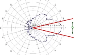
VSWR Tolerance Target
Voltage Standing Wave Ratio (VSWR) measures how efficiently your antenna system transfers RF energy. When impedance mismatches occur, power reflects back toward the transmitter instead of radiating outward. A perfect match is 1:1, but real-world systems tolerate higher values. For reference, a common cellular base station antenna must maintain <1.5:1 VSWR across operating bands to avoid dropped calls. Even small mismatches matter: a seemingly mild 2:1 VSWR wastes 11% of your transmitter power as heat and reflected energy. In high-power systems like broadcast towers (10kW+), poor VSWR can literally melt connectors within minutes.
VSWR Isn’t Just a Number – It’s System Health: High VSWR indicates energy bouncing between your transmitter and antenna. This causes three concrete problems:
- Reduced radiated power (direct range/coverage impact)
- Signal distortion (higher bit error rates in data links)
- Accelerated transmitter failure due to reflected power overheating amplifiers
Operational Tolerance Standards:
| VSWR | Power Loss | Typical Application Tolerance | Critical Risk |
|---|---|---|---|
| 1.0:1 | 0% | Lab/test ideal | Physically impossible |
| 1.5:1 | 4% | Industry gold standard (Cell towers, mission-critical) |
Negligible with good design |
| 2.0:1 | 11% | Commercial baseline (Wi-Fi APs, industrial radios) |
Reduced range; transmitter stress |
| 3.0:1 | 25% | Marginal systems (Low-cost IoT, short-range) |
Amplifier overheating probable |
| >5.0:1 | >44% | System failure threshold | Immediate hardware damage risk |
Why VSWR Changes (and Why Sweep Tests Matter): Your antenna’s VSWR isn’t static. These factors shift it:
- Frequency: Performance varies across operating bands. A 5G antenna might show 1.3:1 at 3.5 GHz but degrade to 2.4:1 at 3.7 GHz. Always check full bandwidth specs.
- Installation: Cable bends, crushed connectors, or moisture ingress destroy impedance matching. A perfect bench-tested antenna may hit 3:1 when deployed.
- Environmental: Nearby metal, walls, or even ice buildup alter antenna resonance. Tower-top antennas require environmental seals.
Practical Mitigation Strategies:
- Design Stage: Specify antennas with VSWR ≤2.0:1 across your entire frequency band. Don’t accept “typical” values – demand sweep charts.
- Installation: Use high-quality cables (Heliax for >5GHz), torque connectors properly, and avoid sharp bends (>10x cable radius rule).
- Maintenance: Monitor transmit reflected power on critical systems. Many radios provide this telemetry. A sudden VSWR spike often indicates connector corrosion or physical damage.
Bandwidth Match Requirement
Bandwidth defines the range of frequencies an antenna can operate within while maintaining performance. If your antenna’s bandwidth is too narrow for your application, you’ll face sudden signal drops at band edges – like an LTE device losing 4G connectivity when it hops from 700 MHz to 2.6 GHz frequencies. For example, a typical Wi-Fi 6 router requires ≥500 MHz bandwidth (5.15–5.85 GHz) to support all channels. Using an antenna with only 300 MHz bandwidth here forces tradeoffs: either sacrifice channel availability (losing DFS bands) or suffer 40%+ throughput reduction on high-frequency channels due to degraded gain and VSWR.
Why Bandwidth Matching Matters
- Frequency agility is non-negotiable in modern systems: A 5G NR antenna must handle 600 MHz to 6 GHz across fragmented spectrum allocations. If bandwidth can’t cover n77 (3.3–4.2 GHz) and n261 (27.5–28.35 GHz), your device fails carrier certification.
- Bandwidth defines real-world usability: An AM/FM broadcast antenna rated for 88–108 MHz seems sufficient until you realize its VSWR spikes to 4:1 at the band edges. This creates dead zones for stations at 87.9 MHz or 107.9 MHz despite being “within spec.”
- Narrow bandwidth kills efficiency: When operating outside an antenna’s optimal bandwidth range, impedance mismatch causes reflected power. At 70% bandwidth utilization (e.g., forcing a 100 MHz-wide antenna to handle 140 MHz), expect 15–20% efficiency loss as energy converts to heat instead of radiation.
Critical Bandwidth Benchmarks by Application
- Cellular IoT (NB-IoT/LTE-M): Needs 60–100 MHz at 700/900/1800 MHz bands. Narrower antennas cause handoff failures between cells.
- Industrial Bluetooth 5: Requires 80 MHz bandwidth (2.402–2.482 GHz) to support all 40 channels. Units sold in Japan add 2.472–2.495 GHz – without this extra 23 MHz, devices fail regional compliance.
- Multiband Wi-Fi 7: Demands three separate bandwidths: 130 MHz (2.4 GHz), 700 MHz (5 GHz), and 1.2 GHz (6 GHz). Compromising on 6 GHz bandwidth prevents 320 MHz channel operation.
Polarization Type Choice
Polarization defines the orientation of the radio waves your antenna emits and receives. Mismatched polarization between transmitter and receiver causes significant signal loss – up to 20 dB (99% power loss!) for cross-polarized antennas. Real-world example: A warehouse drone using horizontally polarized video transmission will lose critical telemetry if the base station antenna mounts vertically. Modern 5G FR1 systems often use ±45° dual polarization to boost reliability in cluttered urban environments, leveraging multipath reflections that would cripple single-polarized links.
Polarization Fundamentals & Performance Impact
Antennas radiate electromagnetic waves with specific electric field orientations. Common types include:
- Vertical: Standard for most mobile radios, base stations (e.g., FM broadcast, walkie-talkies). Waves travel perpendicular to the earth’s surface.
- Horizontal: Used in point-to-point microwave links (e.g., Wi-Fi bridges, TV broadcasting). Less prone to ground reflection interference.
- Circular (RHCP/LHCP): Spiraling waves ideal for satellites and UAVs where orientation changes constantly. GPS antennas use RHCP.
- Dual/Slant (±45°): Dominates cellular infrastructure (4G/5G), providing polarization diversity to handle device rotation without link drops.
Mismatch Penalties Explained:
| Scenario | Polarization Loss | Equivalent Power Drop | Use Case Impact |
|---|---|---|---|
| Tx Vertical ↔ Rx Vertical | 0 dB | None | Optimal mobile-to-base communication |
| Tx Vertical ↔ Rx Horizontal | 20-30 dB | 99-99.9% loss | Critical control signal failure (drones, industrial IoT) |
| Tx Vertical ↔ Rx Slant 45° | 3 dB | 50% loss | Acceptable in multi-antenna MIMO systems |
| Tx RHCP ↔ Rx LHCP | 25+ dB | Near-total loss | Satellite downlink failure if ground station polarity reversed |
Environmental Interference & Polarization
Choosing the right polarization mitigates real-world noise:
- Multipath Rejection: Circular polarization resists interference from ground/object reflections better than linear. Helicopter telemetry links use RHCP to reduce dropouts during banking.
- Industrial Noise Immunity: Motors, generators emit vertically polarized noise. Horizontal polarization in factory sensors cuts RFI by 6-10 dB.
- Atmospheric Effects: Rain can twist polarization (depolarization). Ku-band satellite systems need ±45° or circular pol to maintain uptime during storms.
Application-Driven Selection Guide
| System Type | Recommended Polarization | Why It Matters |
|---|---|---|
| Fixed Point-to-Point Links | Identical linear (H or V) | Maintains <0.5 dB loss; directional links require precision |
| Cellular Macro/Micro Cells | Dual slant (±45°) | Enables MIMO spatial multiplexing; tolerates device rotation |
| UAV/Drone Control | Circular (RHCP) | Unaffected by vehicle pitch/yaw/roll movements |
| Satellite Ground Stations | Circular (match satellite) | GPS: RHCP; Starlink: LHCP/Dual – check documentation! |
| AM/FM Broadcast Receivers | Vertical | Matches transmitter polarization standard |
Circular Tradeoff Note: While RHCP/LHCP solves orientation shifts, its antennas have inherently ~3 dB lower gain than equivalent linear designs. Don’t use circular pol for fixed links needing maximum range unless reflections are unavoidable.
Radiation Pattern Suitability
An antenna’s radiation pattern is a 3D map showing where its signal goes – and crucially, where it doesn’t. Choosing the wrong pattern wastes power and causes dead zones. For example, a ceiling-mounted Wi-Fi access point using a high-gain directional antenna (15° beamwidth) creates signal voids below desks despite strong hallway signal. Conversely, a low-gain omni antenna on a weather sensor buried in a cornfield loses 30-50% range compared to a properly elevated directional antenna overcoming foliage attenuation. Patterns directly determine field reliability and deployment cost.
Why the Shape Matters
- Directional antennas (e.g., Yagi, panel, parabolic) concentrate energy into beams like spotlights. A 24 dBi parabolic dish used in point-to-point microwave links typically has 10°–15° beamwidth – align it within ±2° or miss your target completely. Ideal for bridge monitoring sensors needing kilometers of range between fixed points.
- Omnidirectional antennas radiate like bare lightbulbs, giving 360° horizontal coverage. But vertical coverage varies: cheap rubber duck antennas suffer -30 dB nulls above/below, while ground plane antennas flatten this for better satellite/GPS reception.
- Sector antennas (60°–120° horizontal beamwidth) are cellular industry staples. Mounted on towers, three panels cover 360° without the blind spots common in six narrow-beam solutions.
”A 3 dB gain increase always cuts beamwidth in half – physics trades coverage breadth for reach.”
Real-World Pattern Pitfalls
Ignoring pattern-environment interactions causes costly failures:
- Ground reflections skew low-angle radiation. A highway traffic camera antenna mounted <3m high sees pattern distortion >6 dB from pavement reflections, creating inconsistent detection zones.
- Multipath kills nulls: Urban 5G small cells using high-gain antennas suffer dropped calls at beam edges where nulls intersect reflected signals. Modern antennas deliberately create “pattern ripple” to mitigate this.
- Vertical-plane blind spots matter: Warehouse drone controllers need consistent vertical coverage (+45° to -30°). Dome antennas often sacrifice 40% gain for this spherical pattern – critical when banking.
Application-Specific Validation
Test patterns against your physical reality:
- Outdoor industrial IoT: Directional antennas beat foliage/building blockage. A 10 dBi Yagi with 60° beamwidth reliably reaches 1.2 km across forests where omnis fail at 500 m.
- Vehicular telematics: Dome (hemispherical) antennas maintain connectivity during pitch/roll. An 8 dBic gain variant outperforms 12 dBi flat panels that lose signal when trucks tilt.
- Indoor manufacturing: Ceiling-down tilt pattern antennas focus energy toward factory floors. A panel antenna with 30° down-tilt at 2.4 GHz delivers 25% better RSSI at machine level vs. standard omni.
Key Takeaway: Don’t gamble on generic radiation patterns. Site geometry dictates antenna shape. Validate patterns using EM simulation tools (like FEKO) or real-time spectrum analyzers. For dynamic environments (drones, vehicles), prioritize gain consistency across critical angles over peak dBi values. Remember: a pattern mismatch of 10 dB costs you 90% of your useful signal in dead zones – always overlay pattern plots on deployment blueprints before installation.


