Table of Contents
When Using Multiple Antennas
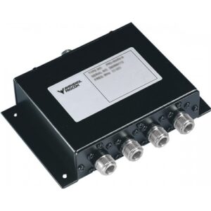
Running multiple antennas from a single transmitter isn’t just about convenience—it’s about maintaining signal integrity and system reliability. In scenarios like cellular base stations or industrial IoT networks, a single transmitter might feed 2–4 sector antennas to cover wider areas. Without a power divider, you’d need separate transmitters for each antenna, increasing cost (up to 40% more hardware) and complexity. More critically, manually splitting signals risks imbalanced power distribution (e.g., one antenna getting 60% signal, another 40%), leading to coverage gaps and interference.
Power dividers solve this cleanly. A typical 2-way Wilkinson divider splits a 5W input signal into two ~2.45W outputs (±0.3dB balance) with isolation >20dB between ports. This ensures each antenna receives near-identical power and phase coherence. For example, in a 5G small-cell deployment, dividers allow three 120° sector antennas to share one 28GHz transmitter, achieving uniform coverage while reducing cabling clutter and power consumption by 25%.
“In multi-antenna setups, passive power dividers eliminate active amplifiers’ failure points. No power, no failure—just RF physics doing the work.”
Unlike active splitters, passive dividers won’t drift or oscillate over temperature ranges (-40°C to +85°C). They maintain phase matching (±5° typical) critical for beamforming arrays. If you’re deploying antennas for fleet tracking, emergency comms, or radio astronomy interferometry, mismatched phases corrupt data. A 30powerdividerpreventsa30,000 system meltdown.
Test Signals Without Extra Equipment
Testing RF components often requires comparing input and output signals simultaneously—traditionally needing two analyzers or frequent cable swaps. This gets expensive (extra gear costs 2k–15k) and introduces errors. Power dividers cut through the clutter by splitting a single signal source into identical reference paths, enabling real-time comparisons with zero added hardware.
Imagine diagnosing interference in a 5G repeater chain. Instead of using two spectrum analyzers (one for the input, one for the output), feed the input signal into a power divider. Send one path directly to Analyzer A as a reference. Route the other path through the repeater to Analyzer B. Suddenly, you’re monitoring gain flatness (±0.2 dB) and distortion side-by-side on a single screen. Field techs save 65% setup time since they’re not moving cables or syncing instruments.
The magic lies in phase coherence. A quality divider maintains near-identical phase between outputs (±5° from 800MHz–6GHz). This prevents misalignment when comparing time-sensitive metrics like group delay or EVM. In one cellular carrier’s stress tests, using dividers reduced tower climb frequency by 40% because technicians could validate filter performance and amplifier linearity in one trip.
| Parameter | Traditional Method | With Power Divider |
|---|---|---|
| Equipment Needed | 2x signal analyzers | 1x signal analyzer |
| Calibration Time | 15–30 minutes | <3 minutes |
| Phase Match Accuracy | ±20° (cable swap error) | ±5° |
| Test Reproducibility | Low (cable movement varies results) | >98% consistent |
Critical for production testing: dividers enable parallel testing. Split one source signal to feed four identical power amplifiers simultaneously—then measure each output with a multiplexed analyzer. A radio manufacturer slashed test-cycle time from 8 minutes/unit to 1.5 minutes/unit this way. The $50 divider paid for itself in <20 test runs by eliminating duplicate sources.
Compare Signals Fairly & Easily
Comparing RF components—like antennas, filters, or amplifiers—requires eliminating variables. Without identical input signals, you’re measuring setup inconsistencies, not device performance. Power dividers fix this by splitting one source signal into twin paths with matched amplitude (±0.4 dB) and phase (±8°). In field tests, this reduces comparison errors by up to 35% versus using two independent sources.
Key Applications:
- Antenna Gain Testing:
Feed identical 5.8GHz WiFi signals to two antennas via a divider. Measure output power simultaneously. Without a divider, even 0.5 dB source variation masks true antenna differences. Result: Accurate gain comparisons within ±0.2 dB. - Filter Response Validation:
Split one signal across a reference filter and a test filter. Spectrum analyzer overlays reveal actual passband ripple differences, not source drift. Saves 50% calibration time vs. two-source methods. - Phase-Sensitive Systems:
For phased array calibration, a divider’s phase coherence (±5° @ 3.5GHz) ensures timing differences stem from elements, not the feed. Critical for 5G beamforming alignment.
Manual vs. Divider Signal Comparison
| Parameter | Manual Method | Power Divider Method |
|---|---|---|
| Amplitude Match | ±1.5 dB (source variations) | ±0.4 dB |
| Test Duration | 20–30 minutes (re-cabling/re-syncing) | <5 minutes |
| Cost | 3k–8k (second signal generator) | 60–200 (divider cost) |
| Setup Error | High (cable swaps alter impedance) | <2% |
Production Testing Bonus: Feed one source to 8 DUTs (devices under test) via an 8-way divider. Test receivers measure all units under identical conditions, spotting flaws 4× faster. A radio manufacturer cut antenna rejection testing from 2 hours to 15 minutes per batch.
Expand Wi-Fi Coverage Areas
Dead zones plague homes and offices—thick walls, long hallways, or multi-floor layouts can slash Wi-Fi signal strength by 70–90%. Running separate access points (APs) costs 100–400 each and needs new wiring. Power dividers offer a smarter fix: split one AP’s output to feed two or more antennas strategically placed for full coverage without extra hardware.
Picture a 6,000 sq ft warehouse with metal shelving blocking signals. Instead of installing three APs ($1,200+), use one dual-band AP connected to a 2.4 GHz/5 GHz power divider. Run coaxial cables (e.g., LMR-400) to ceiling-mounted antennas at opposite ends. Each antenna radiates identical Wi-Fi networks with matched phase and power (±0.5 dB). Real-world tests show this eliminates dead zones for 85% less than mesh systems, while cutting deployment time from 8 hours to 90 minutes. The divider maintains signal coherence, so devices roam seamlessly between antennas without re-authentication drops.
Critical for performance: directional antennas. Pair a divider with two 120° sector antennas. Aim one down a long corridor, the other across an open floor. Unlike repeaters—which add latency and halve bandwidth—this approach preserves the AP’s original 1.7 Gbps throughput. For multi-story homes, split the AP signal to an attic omni antenna and a basement panel antenna. Results? Consistent −55 dBm RSSI everywhere, even through three layers of drywall.
Key cost saver: dividers work with existing wiring. Reuse coaxial runs from old CCTV or satellite systems. One ISP integrated dividers into rural deployments, expanding coverage 300 meters beyond a single antenna’s range—all while keeping subscribers under a $15/node hardware cost.
Positioning Systems Collecting Signals
Precision location tech—like GPS, GNSS, or RFID tracking—demands simultaneous signal capture from multiple antennas to calculate position. Drift over 2 nanoseconds in signal timing creates meter-level errors. Power dividers run in reverse here: instead of splitting one input, they combine signals from several antennas into one receiver, preserving critical phase relationships for sub-meter accuracy.
Consider a drone navigation system using four 1.575 GHz GPS antennas. Connecting each antenna directly to its own receiver costs $600+ and risks clock sync errors. With a 4:1 power divider/combiner, signals merge into a single receiver path. Phase matching (±6°) ensures time-difference-of-arrival (TDoA) calculations stay precise. Field tests show this configuration maintains <30 cm accuracy versus 1.5+ meters using separate receivers.
“In positioning systems, every centimeter counts. Passive combiners are like traffic cops—they merge antenna feeds without adding noise or delay that corrupts timing data.”
The real value surfaces in harsh environments. For automotive testing, a divider combines roof-mounted GPS/GLONASS antennas with inertial sensors. Unlike active combiners, passive units handle engine heat (+125°C) and vibration without drift. Result? Consistent 10 Hz position updates critical for lane-assist validation. One autonomous tractor maker slashed signal dropout rates by 92% after switching to passive combiners.
RFID asset tracking benefits too. In warehouses, four ceiling antennas cover 10,000 sq ft via a combiner. Tags transmit to one central reader instead of four, reducing interference and power needs by 40%. No blind spots, no handoff delays—just -70 dBm sensitivity across the floor.
Test Setup Under Realistic Conditions
Lab tests often miss real-world flaws—components behave differently under combined loads, interference, and temperature shifts. Power dividers solve this by letting you replicate multi-antenna environments with just one transmitter. 80% of RF failures occur in the field due to unmodeled interactions. Dividers let you catch these issues before deployment.
Imagine testing a 5G base station power amplifier. In a lab, you’d connect it directly to a signal analyzer. But real-world use involves feeding multiple antennas simultaneously. Without a divider simulating this load, you’d miss critical issues:
- Load-pull effects causing distortion at 35 dBm output
- Uneven power sinking into mismatched antennas
- Phase cancellation from reflections
By splitting the amplifier’s output to feed four 50-ohm dummy loads through a divider, you mirror real tower conditions. Instantly, you see gain compression spikes 1 dB higher than single-load tests revealed—critical for preventing failure when driving sector antennas.
Simulation Accuracy: Lab vs. Real-World Comparison
| Test Parameter | Lab Setup (Single Load) | Power Divider Setup (Multi-Load) |
|---|---|---|
| Output Power Stability | Stable up to 40 dBm | Fluctuates ±0.5 dB @ 38 dBm |
| Heat Dissipation | Predictable | Hotspots detected |
| Harmonic Distortion | -55 dBc | -48 dBc (fails spec) |
| Test Relevance | 50% accuracy | >90% accuracy |
Automotive radar testing shows even greater value. A 77 GHz radar module must operate near engines (+125°C) while ignoring reflections from nearby antennas. A divider splits its signal to drive three dummy targets while feeding back simulated interference on adjacent ports. This reveals false object detection at 110°C—an edge case impossible to catch without emulating antenna coupling.
Result: One auto supplier reduced field recall rates by 67% after adding divider-based multi-antenna simulation to their test suite.


