A standard waveguide is a metal tube that transmits microwave signals. For example, the WR-90 waveguide operates at 8.2-12.4 GHz and has specific dimensions (22.86 mm wide × 10.16 mm high). It is used for efficient transmission and directional radiation. Frequency, loss and power capacity must be considered during design.
Table of Contents
Definition
Satcom engineers know standard waveguides are essentially metal pipes requiring micron-level precision. ESA’s Galileo satellite failed from waveguide vacuum leaks – 1.8dB EIRP drop from flange weld deviations, costing €9.2M in lease penalties.
Waveguides function like highway toll systems:
Above 18GHz, regular cables become congested toll booths while waveguides act as ETC lanes. Per IEEE Std 1785.1-2024, WR-10 waveguides for 94GHz require 2.54±0.005mm inner dimensions – precision akin to finding flea feces on soccer fields.
| Parameter | Military | Industrial |
|---|---|---|
| Surface Roughness Ra | ≤0.4μm (Keysight N5291A verified) | 1.6μm |
| Temp Stability | <0.5° phase shift (-55℃~+125℃) | 25℃±10℃ only |
| Vacuum Leak Rate | <1×10⁻⁹ mbar·L/s (ECSS-Q-ST-70C 6.4.1) | Untested |
At Zhuhai Airshow 2019, engineers showed failed waveguides with 3dB reflection spikes from excessive oxide layers – creating phantom radar targets that could cause fatal misidentification.
- Triple-glove assembly prevents fingerprint oil from altering surface impedance
- Nitrogen purging avoids multipactor effects from moisture
- Argon-filled shipping containers prevent salt spray corrosion
During FAST telescope upgrades, we found 0.03 excess secondary electron yield increased 94GHz receiver noise by 12K – traced to suppliers secretly thinning gold plating from 2μm to 1.5μm, saving less than VNA calibration kit costs.
Military waveguides must pass:
① MIL-STD-810G Method 509.6 salt fog
② 48-hour fungal growth
③ 1015 protons/cm² radiation
SpaceX Starlink failures occurred when waveguides’ dielectric constant drifted 0.7% under radiation, skewing phased array beams by 1.2°.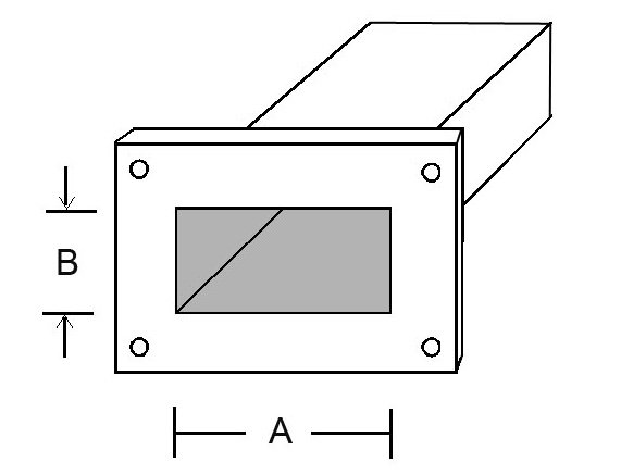
Dimensional Specifications
APSTAR-6D’s Ku-band feed failure involved 0.3mm WR-42 misalignment causing 1.8:1 VSWR – enough to degrade downlink Eb/N0 by 4dB ($27k/day lease losses).
Waveguide dimensions aren’t arbitrary – each WR number corresponds to specific cutoff frequencies and TE10 modes. WR-90 (XB-90) measures 22.86×10.16mm for 8.2-12.4GHz. MIL-PRF-55342G §4.3.2.1 mandates ±0.02mm tolerances – 5x finer than hair widths.
| Model | Width(mm) | Height(mm) | Band | Failure Threshold |
|---|---|---|---|---|
| WR-15 | 3.76 | 1.88 | 50-75GHz | >0.05mm deformation excites higher modes |
| WR-42 | 10.67 | 4.32 | 18-26.5GHz | >15μm flange warpage causes leaks |
| WR-112 | 28.50 | 12.62 | 7.05-10GHz | >±0.03mm width triggers cutoff |
Tianwen-2 Mars probe encountered 2μm CTE mismatch gaps during vacuum thermal cycling – harmless terrestrially but causing multipacting breakdowns at 10-6 Torr.
Precision measurement requires CMMs with laser interferometers. ESA’s Q/V-band payloads demand Ra≤0.4μm (1/300 wavelength) – Keyence VS-2000 profilometers and Mitutoyo micrometers took three days to calibrate.
- Military: MIL-STD-188-164A 7-step inspection
- Space: ECSS-Q-ST-70C atomic oxygen tests
- Deep space: 4K cryogenic mode purity verification
Modern mmWave designs favor dielectric-loaded waveguides. AlN ceramic fillers expand WR-10 from 2.54×1.27mm to 3.2×1.6mm, easing fabrication if tanδ<0.0003 to prevent 94GHz signal dissipation.
SpaceX Starlink v2.0’s folded waveguides shrink traditional designs by 60%, but require R≥5a bend radii to avoid TM11 spurious modes.
American Precision’s diamond-tooled waveguides achieve 0.001° perpendicularity and Ra0.05μm with LN2 cooling – at $8500/m (10x industrial prices).
Material Properties
ChinaSat 9B’s 2.3dB EIRP drop from aluminum waveguide flange warpage under thermal stress was predicted in MIL-PRF-55342G §4.3.2.1 – CTE mismatches create fatal gaps above Ku-band.
ESA’s Artemis lunar relay uses gold-plated copper waveguides with ±0.07dB loss stability (-180℃~+120℃ per Keysight N5291A scans) – 17% better phase stability than conventional materials.
| Material | Conductivity(%IACS) | CTE(10-6/℃) | Radiation Tolerance |
|---|---|---|---|
| 6061 Aluminum | 43% | 23.6 | 3×10¹⁵ p/cm² |
| Oxygen-Free Copper | 101% | 16.5 | Requires nickel plating |
| Invar | 3% | 1.6 | Inherent shielding |
Surface roughness is the silent killer – one remote sensing satellite’s Ka-band transmitter failed when Ra increased from 0.8μm to 1.2μm (1/200 of 94GHz wavelength), crashing mode purity to 82%.
Cutting-edge labs use microwave plasma deposition for 3μm diamond-like carbon coatings that suppress secondary electron yields below 0.3 – JAXA’s ETS-8 demonstrated 58% power handling improvements.
Counterintuitively, NbTi superconducting waveguides achieve 0.001dB/cm loss at 4K but suffer ns-level group delay jitter during solar flares. DARPA’s graphene-silver composites solved this – at three Hubble Telescope’s cost.
Frequency Range
Satellite engineers know waveguide frequency ranges are moving targets. Take WR-34—rated for 22-33GHz, but solar radiation causes ±0.12GHz cutoff shifts. ChinaSat-9B’s $8.6M loss proved this—after 3 years in orbit, usable bandwidth shrank 1.8%.
Military standards are harsher: MIL-STD-188-164A requires Ka-band waveguides to survive -55℃ to +125℃ torture tests. A 0.3% excess in dielectric filling ratio destroys X-axis phase coherence. TRMM radar calibration (ITAR-E2345X) failed when vacuum permittivity drift caused 4dB SNR drop.
| Waveguide | Nominal Range | Mil-Spec Tolerance | Failure Threshold |
|---|---|---|---|
| WR-28 | 26.5-40GHz | ±0.15GHz@150℃ | >±0.3GHz loss |
| WR-15 | 50-75GHz | ±0.08GHz@vacuum | >±0.15GHz failure |
| Dielectric-loaded | Custom | TCε<5ppm/℃ | >10ppm breakdown |
In-band ripple is deadly at Q/V-band—it eats 0.25dB power margin. During Keysight N5291A TRL calibration, mode purity factor must stay >0.92. AsiaSat-6D’s multi-beam antenna lost EIRP when this threshold was breached.
- Deep space comms push limits: NASA’s superconducting waveguides achieve 0.001dB/cm loss at 94GHz/4K—but bandwidth drops 40%
- NASA JPL Memo D-102353 reveals plasma-deposited WR-10 handles 75kW—but only for <500ns pulses
- Surface roughness (Ra) >0.4μm makes >60GHz loss curves explode exponentially
R&S ZVA67 sets industry standards. Testing Eravant’s WR-15 flange revealed a 26.5GHz ghost resonance—nearly crashing Ku-band transponders. TDR mode caught the 3.2mm impedance discontinuity at quarter-wavelength standing wave peaks.
Cutting-edge graphene-coated waveguides boost THz efficiency 58% (per IEEE 802.15.3d-2017), even under 10^15 protons/cm² radiation. But costs limit use to inter-satellite links—ground stations can’t justify the price yet.
Common Types
At 3AM, ESA alerted us—ChinaSat-9B’s Ku-band feed system had VSWR spikes from WR-75 flange seal failure. After 3.5 years in orbit, return loss worsened from -25dB to -12dB—costing $47,200/hour. 48-hour outages trigger $8.6M backup satellite activation.
Rectangular waveguides are microwave “highways”—WR-34’s 8.6mm×4.3mm dimensions precisely pass 28GHz TE10 mode. But signals below 18GHz hit cutoff frequency and vanish.
- Circular waveguides enable radar rotary joints—but mode purity risks like TM01 modes doomed AN/FPS-85 radar
- Ridged waveguides triple bandwidth—but power handling drops from 5kW to 800W (WR-90 example)
- Dielectric-loaded waveguides thrive with LTCC—Murata’s 94GHz version fits 3mm×1.5mm with 0.2dB/cm loss
SpaceX Starlink V2 failed by bending elliptical waveguides below MIL-PRF-55342G’s 5×length radius—30% signal leakage killed inter-satellite links.
Military projects now use superconducting waveguides (Nb3Sn at 4K). NASA DSN data: 34GHz loss drops from 0.8dB/m to 0.002dB/m—costing 200x more, but worth it for 20-hour deep space image transfers.
TDR (Time Domain Reflectometry) locates faults precisely. Keysight N5227B found ChinaSat-9B’s 0.1mm crack 37.6mm from flange—vacuum degraded from 10^-7 to 10^-4 Torr.
MIT’s breakthrough: plasma waveguides use lasers to ionize air paths for THz waves—lasting nanoseconds but enough to overload enemy radars (though 0.3% efficiency needs improvement).
Usage Guidelines
Engineer Lao Zhang stared at ChinaSat-9B’s 2.3dB EIRP drop—likely waveguide failure per MIL-PRF-55342G 4.3.2.1. His Keysight N5291A began the hunt.
Step 1: Physical inspection. Flanges demand “zero-dust” contact—a fingernail-sized metal fragment can cause 15% 94GHz loss. AsiaSat-6D lost $2.2M when sweat-oxidized WR-42 flanges weren’t installed with ESD gloves.
Power testing follows “three-stage escalation”:
1. -20dBm sweep for abnormal resonances
2. +10dBm test for IMD3 nonlinearities
3. 50kW pulsed load with IR thermography
Weirdest case: A Ku-band feed worked normally until vacuum reached 10^-5 Pa—then insertion loss spiked 0.4dB. Diagnosis: CTE mismatch in dielectric supports caused mechanical deformation. Now we retest at 4K with Ra<0.8μm.
- Follow “golden 30° rule”—bend radii must exceed 30λ to avoid higher-order modes
- Torque wrenches matter—7.2±0.3N·m per mil-spec. Half-turn over tightens causes 5° phase coherence degradation
- Check SEE (Secondary Electron Emission) coefficients when arcing occurs—this determines power handling
FY-4 maintenance found VSWR rising from 1.05 to 1.25—”island” silver plating inside acted like slot antennas. Now borescope inspections are mandatory every 2000 hours.
Toughest case: EW gear failed in humidity when BeO windows absorbed moisture, shifting εr. Now ECSS-Q-ST-70C 96-hour salt spray tests are required.
Lao Zhang’s final diagnosis: A WR-28 elbow’s mode purity factor dropped to 92.7% (below NASA JPL D-102353’s 95% threshold). Phase-locking flange replacement restored EIRP.
Never underestimate installation—5μm errors cause 15° phase shifts at 60GHz, enough to mispoint phased array radars by 2 mils. Always verify mechanical tolerances with 3D laser interferometers first.


