What is the waveguide effect
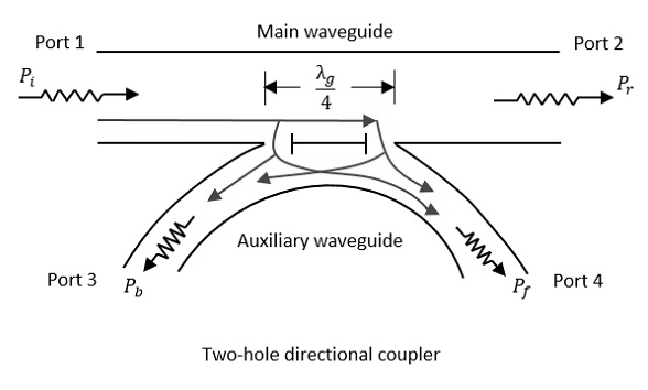
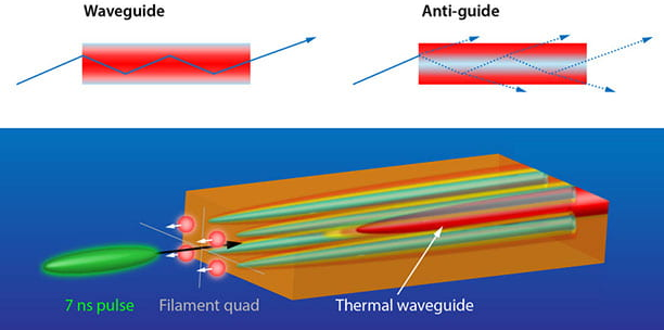
The waveguide effect occurs when electromagnetic waves (e.g., microwaves at 2.45GHz or light in fiber optics) are confined and propagated along a physical structure, reducing signal loss (<0.3dB/km in optical fibers). This effect relies on total internal reflection (critical angle ~82° for glass/air) or conductive boundaries (e.g., rectangular metal waveguides). It enables efficient energy transfer […]
What is the waveguide effect Read More »