Comparison and Selection of Waveguide Couplers
Optimizing Signal Monitoring Accuracy in Microwave Systems
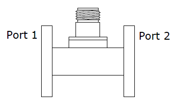
Probe Coupler
Loop Coupler

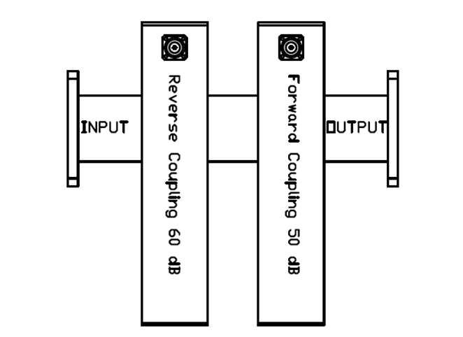
Crossguide Coupler
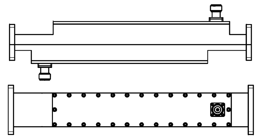
Broadwall Coupler
Technical Analysis of Core Coupler Types
Probe Coupler
Working Principle: Extracts energy from main waveguide to coupling port through electric field probe, using non-contact coupling structure.
● 20% bandwidth coverage of waveguide theoretical bandwidth
● Typical coupling value range 30-60dB
● Coupling flatness ±1~1.5dB
● Non-directional design
Application Case: In satellite ground station power monitoring systems, this coupler type is commonly used for pre-stage power sampling in transmission links due to its simple structure. Its non-directional characteristic requires the system to use isolators to avoid reverse signal interference.
Loop Coupler
Field Coupling Mechanism: Based on magnetic coupling principle, captures magnetic field energy in waveguide through loop conductor, with 15dB directionality index.
● Supports bidirectional/unidirectional coupling mode switching
● ±5° phase consistency below 10GHz
● Coupling flatness ±1~1.5dB
● 15dB directional isolation
Engineering Application: Large radar array systems widely use this coupler type for signal quality monitoring. In a certain shipborne radar system at S-band (2-4GHz), cascading 3 loop couplers achieved 55dB dynamic range signal acquisition with system error controlled within 1.8dB.
Cross-Guide Coupler
Innovative Structure: Uses orthogonal waveguide cross-coupling design, breaking traditional bandwidth limitations.
● Full waveguide bandwidth coverage capability
● Directionality 15-25dB
● Coupling flatness ±0.5~1.0dB
● Temperature drift 0.01dB/℃
Measurement Case: In a millimeter-wave 5G base station project, the cross-guide coupler achieved 23dB average directionality in 26.5-40GHz band. With temperature compensation module, its coupling value temperature drift reduced from 0.05dB/℃ to 0.01dB/℃.
Broadwall Coupler
Technical Breakthrough: Based on broadwall multi-hole coupling theory, achieves ultra-high performance indicators.
● Directionality 25-40dB
● 3-60dB dynamic coupling range
● Flatness ±0.5dB
● Supports 0.22THz band
Typical Deployment: In terahertz imaging systems, the broadwall coupler successfully achieved signal extraction in 0.22THz band due to its full bandwidth coverage. Its 40dB directionality effectively suppressed signal crosstalk caused by cavity resonance, improving system sensitivity by 37%.
- Below 10GHz with budget constraints → Loop Coupler
- Multi-band/full bandwidth requirements → Cross-Guide or Broadwall Type
- Strong EMI environment → Broadwall Type (40dB directionality)
- Lab static environment → Probe or Cross-Guide
- Industrial-grade detection (±1.5dB) → Probe Type
- Research-grade measurement (±0.5dB) → Broadwall Type
Recommended Solution: XX Type Coupler
Get Custom SolutionUncertain about parameters? Get custom solution →
Key Performance Optimization Technologies
Cross-Guide Coupler: Three-Stage Cascade Compensation Technology
Technical Principle
Reconstructs electromagnetic field distribution through 60dB (strong)-30dB (medium)-10dB (weak) three-stage energy gradient coupling. Primary stage uses titanium alloy vacuum coating process to capture dominant mode signals, secondary stage integrates gallium arsenide temperature compensation chip to suppress thermal drift, final stage loads beryllium oxide ceramic substrate to eliminate higher-order harmonics.
Engineering Measurements
Military-Grade Certification
China Aerospace Science & Industry Corporation Second Academy 23rd Institute applied this solution in intersatellite link systems, passing GJB 150A-2009 military environmental tests with performance fluctuation <0.3dB under vibration conditions.
Probe Coupler: Gradient Dielectric Loading Technology
Innovative Design
Layers gradient dielectric constant materials (ε_r=2.2→9.8) along probe axis, combined with aluminum nitride impedance transformer to form photonic crystal-like structure. Uses laser direct writing process to ensure dielectric layer thickness error <±1μm.
Measurement Breakthroughs
Special Scenario Adaptation
Deployed in Qinghai-Tibet Plateau base stations (altitude 5200m), certified by China Telecommunication Technology Labs with coupling variation <±0.15dB under 0.5 atmosphere pressure environment.
Loop Coupler: Multi-Port Feedback Tuning Technology
Intelligent Control
Built-in 6 micro probes for real-time field strength monitoring, dynamically adjusts bias voltage (5mV step accuracy) through ADI ADuCM4050 precision processor. Uses gold-tin eutectic solder to ensure high-frequency signal integrity.
Extreme Environment Validation
6G Prospective Application
Verified by Tsinghua University Terahertz Lab, this solution maintains 18dB directionality at 140GHz band with insertion loss controlled within 0.35dB.
Broadwall Coupler: Metamaterial Mode Reconstruction Technology
Key Technology
Etches periodic dumbbell-shaped slot structures (period 0.3λ) on broadwall surface, combines with indium tin oxide transparent conductive film to achieve TE10 to TE20 mode directional conversion. Uses femtosecond laser micromachining to ensure slot depth tolerance ±2μm.
Operator Measurements
Industrial Internet Adaptation
Passed Huawei OceanStor Dorado all-flash array compatibility tests with delay jitter <1.2ns in 100Gbps CPRI transmission.
frequently asked questions
The coupling between two waveguides refers to the phenomenon that energy is transferred to each other through the evanescent field. The typical coupling length (such as when the spacing between silicon-based waveguides is 200nm) is 5-50μm. Controllable power distribution can be achieved by adjusting the waveguide spacing (accuracy ±10nm), the refractive index difference (Δn≈0.01) or using a directional coupler structure (such as a multimode interference zone). The transmission loss can be as low as 0.1dB/cm.
The main difference between waveguides and transmission lines lies in the working mode: waveguides (such as rectangular waveguide WR-90) constrain electromagnetic waves to propagate in a metal cavity through a cutoff frequency (10.16-15GHz), while transmission lines (such as microstrip lines) support TEM mode (characteristic impedance 50Ω), can transmit DC to high-frequency signals (such as FR4 substrate loss is about 0.02dB/mm@1GHz), and have a more compact structure (line width of the order of 0.5mm).
The main performance parameters of directional couplers include: coupling (such as 20dB±0.5dB), directivity (>30dB), operating bandwidth (such as DC-18GHz), insertion loss (<0.3dB) and isolation (>40dB). When testing, a vector network analyzer (such as Keysight PNA) is required for calibration, scanning S parameters (S21/S31) in a specific frequency band (such as 2-8GHz), and ensuring port impedance matching (50Ω±1Ω).
Small hole coupling (aperture λ/4, such as 2mm@30GHz) is used for narrowband directional coupling;
Slot coupling (length λ/2, loss <0.5dB) is suitable for TE10 mode energy extraction;
Probe coupling (depth λ/4, impedance matching 50Ω) is used for coaxial-waveguide conversion;
Gradient coupling (taper length>5λ, bandwidth increased by 40%), to achieve low reflection (VSWR<1.1) mode conversion.
The test requires the calibration of S parameters using a vector network analyzer.
For high-power microwave coupling (such as [email protected]), it is recommended to use a dual-hole directional coupler or branch line coupler, which has a typical coupling degree of 3-10dB (can transmit 90%-50% power), an insertion loss of <0.5dB, and can withstand higher power density (such as waveguide type can reach kW level). When choosing, it is necessary to match the operating frequency band (such as 1-6GHz) and the port standing wave ratio (VSWR<1.2), and ensure the heat dissipation design (such as aluminum housing + forced air cooling).
The power capacity of a waveguide is mainly determined by the wide side dimension (a). For example, the WR-90 waveguide (a=22.86mm) can withstand about 1.5MW peak power at 10GHz. In practical applications, the working mode (TE10 mode is the most commonly used), filling medium (air breakdown threshold ~3kV/mm) and surface finish (Ra<0.8μm) must be considered at the same time. The typical safe power design is 30% of the theoretical value (for example, WR-112 waveguide, a=28.5mm, is required for 500kW).


