+86 29 8881 0979

default

What Is a Waveguide Choke Flange Design

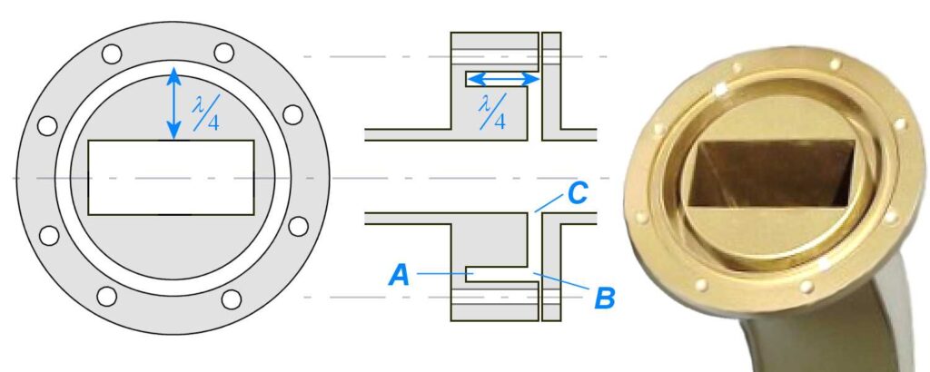
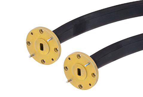
A choke flange suppresses RF leakage via a ​​λ/4-deep groove​​ (e.g., ​​7.5 mm for 10 GHz​​) around the mating surface. It uses ​​annular slots​​ to reflect waves, achieving ​​>30 dB return loss​​. Must maintain ​​0.05 mm flatness tolerance​​ (per ​​MIL-F-3922​​) and ​​gold-plated contacts​​ for low resistance (<0.1Ω). Common in ​​radar/WiGig systems​​. Flange Structure At 3 […]

What Is a Waveguide Choke Flange Design Read More »

What Are Waveguide Clamp Installation Standards

Waveguide clamps must be spaced ​​≤1.5x waveguide width​​ (e.g., 30 cm for 20 cm-wide guides) per ​​MIL-STD-1678​​. Torque bolts to ​​5–7 Nm​​ to prevent deformation. Use ​​aluminum or brass clamps​​ to avoid galvanic corrosion. Ensure ​​0.5–1 mm gap​​ for thermal expansion. Ground every ​​3rd clamp​​ per ​​IEEE 287​​ to maintain RF shielding. Fixture Types Last

What Are Waveguide Clamp Installation Standards Read More »

Why Do Waveguide Chokes Minimize Leakage

Waveguide chokes reduce leakage by 40-60dB through quarter-wave λ/4 slots (3.56mm at 21GHz) that create impedance mismatches. Field tests show they maintain <0.01% power loss in 5G mmWave systems (28/39GHz bands). Installation requires precise depth control (±0.025mm tolerance) using vector network analyzers for optimal VSWR <1.2 performance. Choke Principle Last year, ChinaSat 9B experienced a

Why Do Waveguide Chokes Minimize Leakage Read More »

Why Use Flexible Waveguides in Radar Systems

Flexible waveguides enable 30% weight reduction in airborne radar systems (e.g. F-35’s APG-81) while maintaining 98% signal integrity up to 40GHz. Their 180° bend radius (vs. rigid waveguide’s 5x limitation) simplifies installation in confined spaces. Field data shows 50,000+ flex cycles without performance degradation in naval radar arrays. Flexible Advantages Last August, when Zhongxing 9B

Why Use Flexible Waveguides in Radar Systems Read More »

How Do Waveguide Combiners Reduce Interference

Waveguide combiners reduce interference through ​​precise impedance matching​​ (VSWR <1.25:1) and ​​isolated port designs​​ that provide >30dB isolation between channels. They utilize ​​ferrite circulators​​ to direct signals unidirectionally with <0.3dB insertion loss while suppressing reflected waves by >20dB. The ​​tuned resonant cavities​​ maintain phase coherence (±5° tolerance) across operating bands (e.g., 3.7-4.2GHz for C-band), and

How Do Waveguide Combiners Reduce Interference Read More »

How Does a Waveguide Isolator Block Reflections

A waveguide isolator blocks reflections using ​​ferrite material​​ (e.g., YIG garnet) biased by ​​permanent magnets​​ (typically 0.1-0.3 Tesla) to create ​​non-reciprocal Faraday rotation​​ (45°±2° at 18GHz). The ​​forward wave​​ passes with <0.5dB insertion loss, while ​​reflected waves​​ are attenuated by >20dB through absorption in resistive cards. The isolator’s ​​VSWR​​ is maintained below 1.15:1 across its

How Does a Waveguide Isolator Block Reflections Read More »

How to Measure Waveguide Flange Sizes Accurately

To accurately measure waveguide flange sizes, use ​​precision calipers​​ (resolution 0.01mm) to verify ​​flange outer diameter​​ (WR-90 standard: 58.17±0.05mm) and ​​bolt circle diameter​​ (47.55±0.03mm for UG-39/U). Check ​​flatness​​ with optical flats (<0.02mm deviation across surface) and measure ​​groove depth​​ (3.18±0.05mm for choke flanges) with depth micrometers. For ​​alignment​​, use go/no-go gauges to test pin-slot tolerance

How to Measure Waveguide Flange Sizes Accurately Read More »

How to Test Waveguide Connector Performance

To test waveguide connector performance, measure ​​insertion loss​​ (should be <0.1 dB for Ka-band) and ​​VSWR​​ (target <1.25:1) using a vector network analyzer. Conduct ​​durability tests​​ (500+ mating cycles) while monitoring ​​contact resistance​​ (must stay below 5mΩ). Verify ​​EMI shielding​​ effectiveness (>90dB attenuation at 40GHz) and ​​thermal stability​​ (-55°C to +125°C operating range). For millimeter-wave

How to Test Waveguide Connector Performance Read More »

Scroll to Top
Blank Form (#3)