default

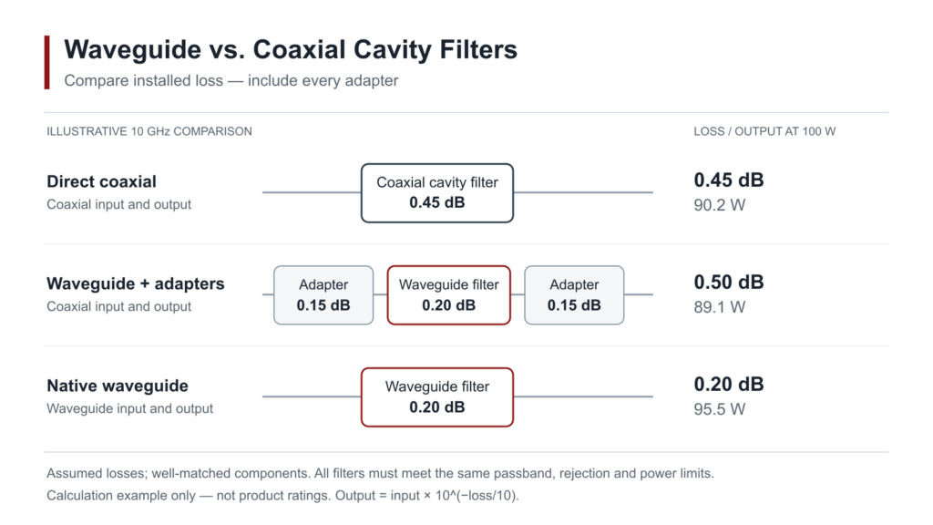
Illustrative 10 GHz installed loss comparison for coaxial cavity and waveguide filters, including adapter losses

Waveguide vs. Coaxial Cavity Filters: Selection by Frequency, Power & Interface

Choose a coaxial cavity filter when lower-frequency operation, compact packaging, and direct 50 Ω connections are the main constraints. Favor waveguide at microwave and millimeter-wave frequencies when low loss, power handling, or existing waveguide ports justify it. There is no universal GHz or watt threshold. Compare both designs at the same bandwidth and rejection requirements,

Waveguide vs. Coaxial Cavity Filters: Selection by Frequency, Power & Interface Read More »

What Should a Waveguide Component Acceptance Report Include?

A waveguide component acceptance report needs six things: part identification, agreed limits, measured results, test conditions, calibration and uncertainty records, and an acceptance decision. Ask for results linked to the delivered serial numbers. An unlabeled plot or a model-wide specification sheet cannot replace those records. Use this checklist as a purchasing guide. Your drawing, purchase

What Should a Waveguide Component Acceptance Report Include? Read More »

Waveguide Quick Disconnect Selection | Compatibility, Assembly, Signal Integrity

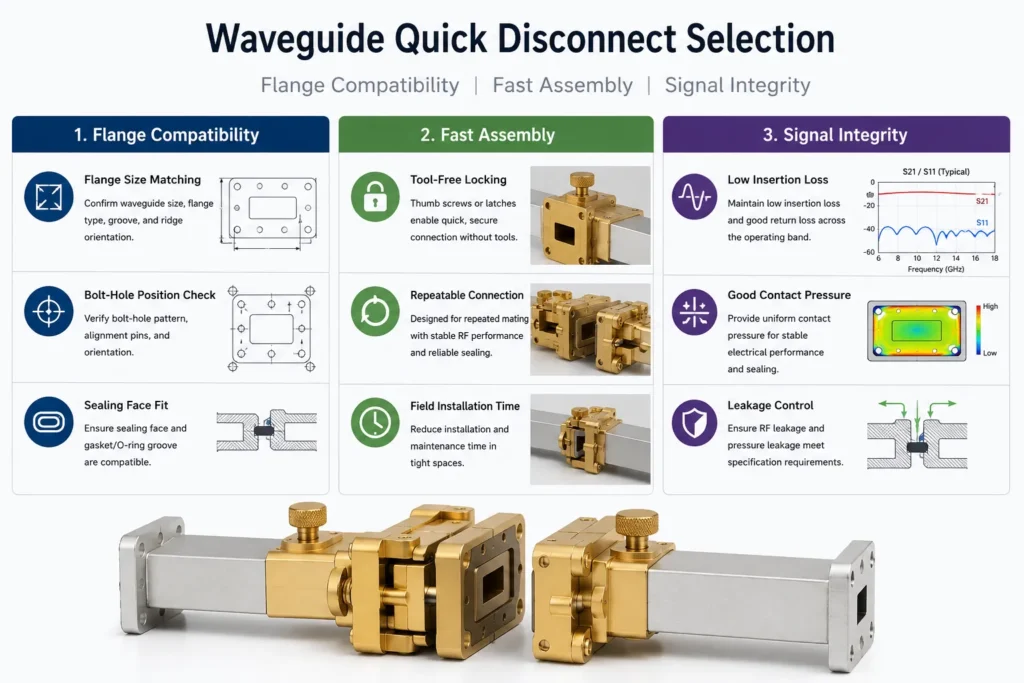
Select a waveguide quick disconnect by its exact mating interface, locking arrangement and verified RF performance after reconnection. For a pressurized line, add separate pressure and leakage limits. A fast latch does not establish flange compatibility, low insertion loss or a gas-tight seal. Selection gate Evidence to request Compatible interface Dimensioned aperture, flange, locating features,

Waveguide Quick Disconnect Selection | Compatibility, Assembly, Signal Integrity Read More »

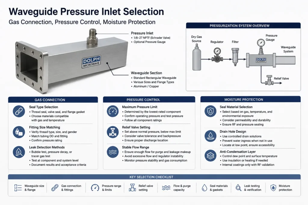
Waveguide Pressure Inlet Selection | Gas Connection, Pressure Control, Moisture Protection

Choose a waveguide pressure inlet by the waveguide and flange drawing, exact gas connection, complete assembly pressure limit and required gas dryness. Then size the supply and protection system for purging, leakage makeup and credible regulator failure. The inlet’s catalog pressure is not automatically the operating setpoint for the line. Use clean, dry air or

Waveguide Pressure Inlet Selection | Gas Connection, Pressure Control, Moisture Protection Read More »

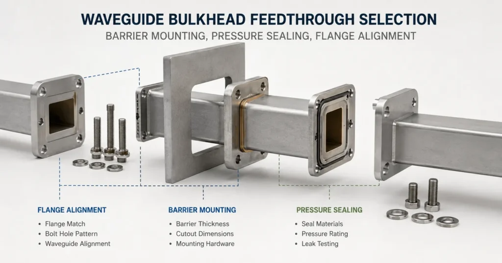
Waveguide Bulkhead Feedthrough Selection | Barrier Mounting, Pressure Sealing, Flange Alignment

Select a waveguide bulkhead feedthrough by the finished wall stack, mounting cutout, mating flange drawings and required sealing boundary. Then verify mechanical fit, RF performance and any pressure or leakage requirement in the installed configuration. A bulkhead feedthrough carries the waveguide through a wall or panel. An open RF bore does not separate the gas

Waveguide Bulkhead Feedthrough Selection | Barrier Mounting, Pressure Sealing, Flange Alignment Read More »

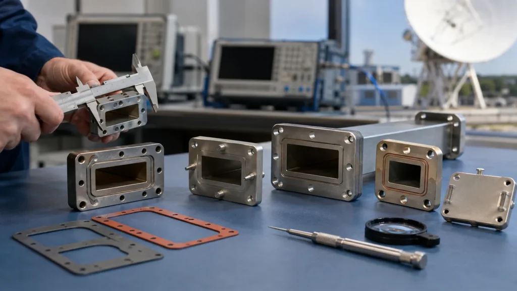
Waveguide Flange Size Guide | EIA Standard, IEC Types, Gasket Fit

Choose a waveguide flange by its complete interface drawing, not the WR size alone. Match the RF aperture, bolt and alignment-hole pattern, mating face, gasket groove and fasteners. Two parts marked WR90 can carry the same waveguide size yet require different flange interfaces. IEC 60154-2 covers mechanical dimensions and compatibility for ordinary rectangular waveguide flanges.

Waveguide Flange Size Guide | EIA Standard, IEC Types, Gasket Fit Read More »

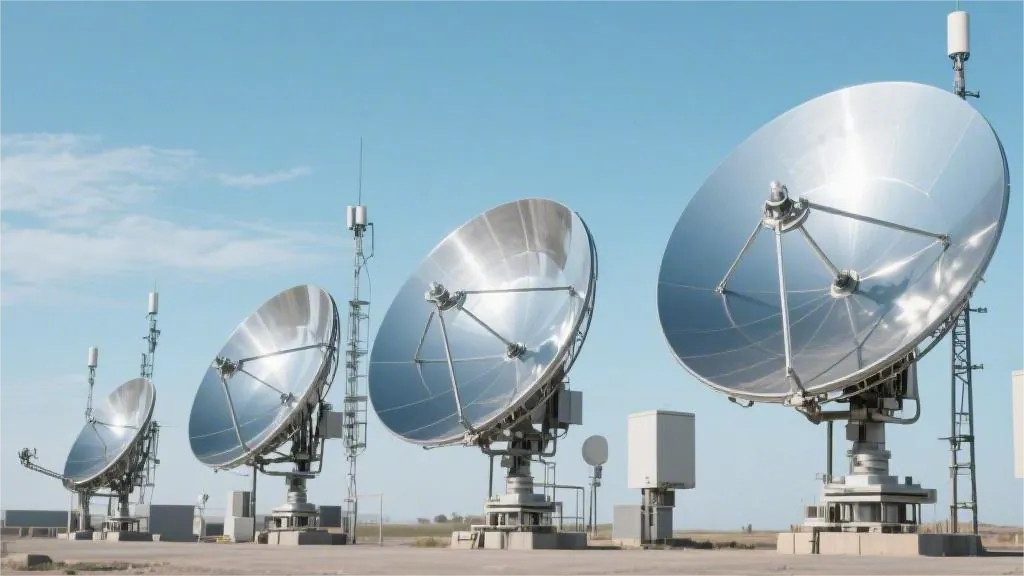
Ku-Band Satellite Antenna Selection | Weather Fade, High Throughput, Dish Size

Select a Ku-band satellite antenna from the operator’s coverage and access requirements, a site-specific link budget and the minimum service rate required during bad weather. Dish diameter alone cannot guarantee 99.9% availability. At equal frequency and aperture efficiency, increasing diameter from 1.2 m to 1.8 m adds about 3.52 dB of gain; whether that closes

Ku-Band Satellite Antenna Selection | Weather Fade, High Throughput, Dish Size Read More »

Flat Panel Satellite Antenna Technology | Metamaterials, Electronic Steering, LEO

A flat-panel satellite antenna steers its beam across a low-profile aperture. Phased arrays and tunable metasurfaces can both do this electronically, but they use different RF architectures. For LEO service, select the terminal by network compatibility, EIRP and G/T across its scan range, tracking performance, and available electrical power—not by panel thickness alone. Metamaterials and

Flat Panel Satellite Antenna Technology | Metamaterials, Electronic Steering, LEO Read More »

Scroll to Top
Blank Form (#3)