A dish antenna’s F/D ratio, also called its focal ratio, is the focal length divided by the reflector diameter. It describes the dish’s proportions: a lower F/D means a deeper reflector, while a higher F/D means a shallower one. For a circular prime-focus dish, F is measured from the reflector’s vertex to its focus, and D is the diameter across its opening.[1] An F/D of 0.40 means the focal length is 40% of the diameter. On a 1.2 m dish, that gives F = 0.48 m.
The practical value is feed matching. F/D determines how wide the dish appears from the focus; together with the diameter, it also gives the focal distance. It does not, by itself, tell you the antenna’s gain or which feed will work at your operating frequency.
Table of Contents
What F and D Stand For
For a centered paraboloidal reflector, the vertex is the deepest point on the reflecting surface. Measure F from that point along the dish axis, not from the rim plane or the back of the mounting bracket. D is the clear aperture diameter. Because both lengths use the same units, F/D has no units.
Two geometrically similar dishes can have the same F/D despite very different diameters. They present the same angular coverage requirement to the feed, but that does not make their feeds interchangeable: frequency, polarization, phase-center location, and radiation pattern must also match. The ARRL guidance specifically calls for choosing a feedhorn for the reflector’s F/D and placing its phase center at the focus.[1]
What the Number Tells You
A deeper dish wraps farther around the feed and needs wider angular illumination. A shallower dish needs narrower illumination and places its focus farther from the vertex for the same diameter. For prime-focus antennas, a university-repository paper describes 0.3 < F/D < 0.6 as a normal practical range; this is a design range, not a mandatory standard or a guarantee of performance.[2]
The following examples assume an ideal, circular, centered paraboloid with D = 1.2 m. Depth d is measured from the rim plane to the vertex. The depth follows from F = D²/(16d).[3] The full rim-to-rim angle at the focus is calculated as 4 × arctan[1/(4 × F/D)], converted to degrees. These are geometry calculations, not product measurements or feed beamwidth specifications.
| F/D | Focal length F | Dish depth d | Full angle seen from the focus |
|---|---|---|---|
| 0.30 | 0.36 m | 0.250 m | 159° |
| 0.35 | 0.42 m | 0.214 m | 142° |
| 0.40 | 0.48 m | 0.188 m | 128° |
| 0.45 | 0.54 m | 0.167 m | 116° |
| 0.50 | 0.60 m | 0.150 m | 106° |
| 0.60 | 0.72 m | 0.125 m | 90° |
For example, changing F/D from 0.30 to 0.50 moves the focus from 0.36 m to 0.60 m from the vertex: an increase of 0.24 m, or about 67%, not a doubling. At F/D = 0.25, the same equations put the focus in the rim plane and give a full coverage angle of 180°. That geometry makes illumination demanding; it does not mean such a reflector or feed is impossible.
What F/D Changes on Your Dish
Feed position
The feed’s phase center should coincide with the reflector focus. The phase center is the effective point from which the feed’s radiation appears to originate; it is not necessarily the horn mouth or its mounting flange. Use the feed documentation for the relevant frequency rather than measuring to an arbitrary mechanical surface. The ARRL article identifies phase-center placement at the focus as the most critical positioning dimension.[1]
Do not treat a fixed millimeter tolerance as universal. A suitable positioning tolerance must come from the antenna and feed design, operating band, and acceptable performance loss. The calculated focus is a starting point for alignment, not a substitute for the manufacturer’s installation specification.
Feed pattern
Choose a microwave feedhorn whose pattern suits the reflector’s angular extent. Ask for illumination data at the actual operating frequencies, including the feed level toward the rim, rather than matching only a catalog F/D label. Too little illumination near the edge leaves part of the aperture underused; radiation extending beyond the rim produces spillover. Aperture illumination also affects gain, beamwidth, and sidelobes, so F/D alone cannot specify these outcomes.[2]
Support structure
A larger F/D places the focus farther from the vertex for a fixed diameter, which can require a more extended feed-support arrangement. University of Cape Town teaching material explicitly notes cumbersome focal supports as a trade-off at large F/D.[4] The vertex-to-focus distance is not automatically the physical length of a support leg; that also depends on where and how the supports attach.
How to Find Your Dish’s F/D
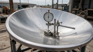
For a circular, centered parabolic reflector with an accessible rim plane, measure the clear diameter D. Place a straightedge across the rim and measure the perpendicular depth d to the vertex of the reflecting surface. Use consistent units and calculate:[3]
F = D² / (16d)
F/D = D / (16d)
A worked measurement example
Suppose a centered dish measures 1.2 m across and 0.190 m deep. This illustrative calculation gives F = 1.44 / 3.04 = 0.474 m, and F/D = 0.474 / 1.2 = 0.395, rounded. The nominal phase-center position is therefore about 0.474 m from the vertex along the axis. This is not a measurement of a commercial antenna.
Depth errors can noticeably change the answer. For a 1.2 m dish with a true depth of 0.150 m, F/D is 0.500. Reading the depth as 0.140 m gives 0.536; reading it as 0.160 m gives 0.469. Recheck the straightedge seating and repeat the depth measurement before deciding that an existing feed mount is wrong. These calculated values assume a true paraboloid and an accurately measured diameter.
A practical focus-check procedure
If you are replacing a feed on an existing centered dish, start by recording the reflector dimensions, operating band, polarization, and the replacement feed’s documented phase-center reference. Keep the original mounting position as a reference until you have checked the geometry.
Where the manufacturer permits axial adjustment, use a stable receive signal and hold pointing, polarization, and receiver settings constant. Move the feed through small, recorded axial adjustments around the predicted position, allowing the reading to settle at each step. Compare positions on both sides of the apparent peak, then secure the mount and check the reading again. Follow the equipment’s safety and installation instructions; the procedure does not require transmitting.
Does the Same Method Work for Offset Dishes?
Not directly. An offset reflector is an off-axis section of a parent paraboloid, so its visible center is not the parent reflector’s vertex. The ARRL treatment uses different measurements and calculations for offset geometry.[1] Do not insert the visible width and center depth into the centered-dish formula and assume the result is the specified F/D. Use the manufacturer’s drawing and confirm how its focal ratio and feed position are defined. Dual-reflector systems likewise require their own feed-placement geometry.
In short, F/D describes reflector proportions, not overall antenna quality. Use it with the diameter to locate the focus, then match the feed’s phase center and illumination pattern to the reflector at the required frequency. When discussing antenna feed-network options, supply the reflector geometry and operating requirements together, rather than an F/D number alone.
Matching a feed to a new or existing reflector? Share the reflector type, diameter, focal length or F/D, operating band, polarization, and waveguide interface to discuss compatible feedhorn and feed-network options.
Request a Technical ReviewReferences
- ARRL, QST, “Parabolic Dishes.” Feed selection, phase-center positioning, and centered versus offset geometry. Read the original PDF. Accessed November 11, 2026.
- International Islamic University Malaysia repository, “Comparative Analysis among Satellite Parabolic Antennas.” Practical prime-focus F/D range and aperture-illumination trade-offs. Read the research paper. Accessed November 11, 2026.
- R. C. Maher, Montana State University, “Parabolic Dish Microphone” (2005). Parabolic focal-length geometry; used here for the geometric equation, not RF feed-performance recommendations. Read the university paper. Accessed November 11, 2026.
- University of Cape Town, “Reflector Antennas.” Focal ratio and feed-support trade-offs. Read the course material. Accessed November 11, 2026.