+86 29 8881 0979

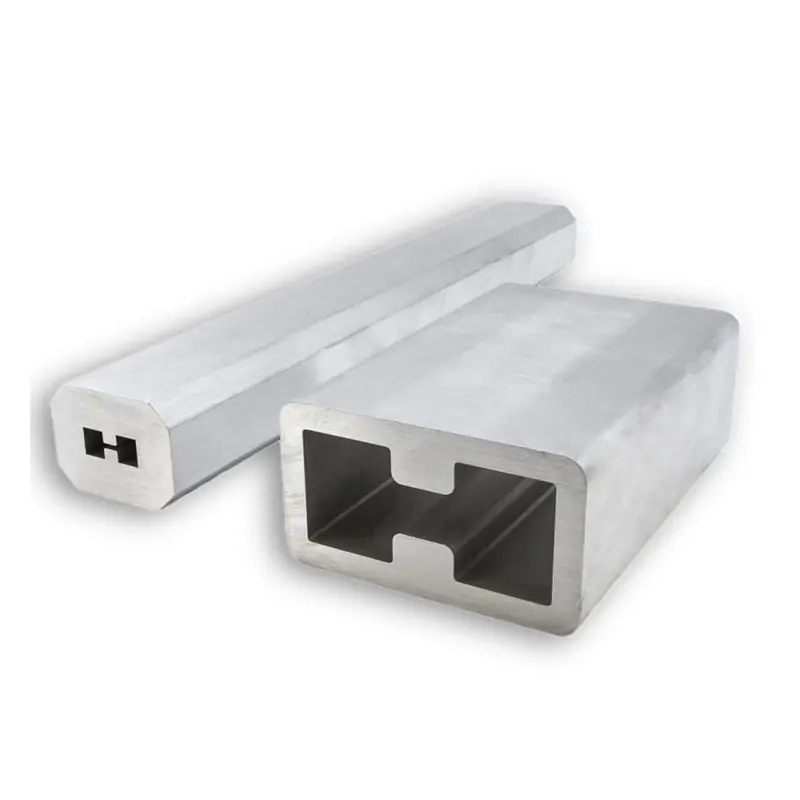
Double-Ridged Waveguide Tube

Waveguide tubes are hollow metallic conduits used to guide electromagnetic waves from one point to another in microwave and RF systems. They are essential for efficiently transmitting high-frequency signals with minimal loss, making them ideal for applications in radar, telecommunications, satellite communication, and scientific research. Waveguide tubes come in various shapes and sizes to accommodate different frequency ranges and system requirements, ensuring optimal performance and signal integrity.

Published Frequency

0.84–40.0 GHz

Waveguide Range

WRD840–WRD180

Published Standards

IEC and EIA

Compatible Flanges

FPWRD / FMWRD

Material Options

Aluminum / Copper

Supply Format

Standard and Custom Lengths

Double-Ridged Waveguide Tube

Broadband Waveguide Tubing for WRD-Series RF Systems

These double-ridged waveguide tubes provide the mechanical transmission path used to route microwave and RF signals in broadband WRD assemblies. Selection begins with the operating band and WRD family, followed by dimensional, material and length requirements.

Published Product Scope

The current range covers thirteen WRD families from WRD840 through WRD180, corresponding to published operating bands from 0.84 GHz to 40.0 GHz.

Waveguide typeDouble-ridged metallic waveguide tube.
Size selectionMatch the complete operating frequency band to the applicable WRD family.
StandardsPublished IEC and EIA designations are listed with each family.
InterfacesFPWRD cover and FMWRD grooved flange families are identified for compatibility review.


Custom Supply Requirements

The product summary lists aluminum and copper options together with standard and customized mechanical configurations. Tube length and final interface details should be defined in the approved drawing or quotation.

MaterialsAluminum or copper, subject to model and project requirements.
LengthsPublished examples include 50 mm, 100 mm and 200 mm; custom lengths can be reviewed.
DimensionsSpecify the required dimensional tolerances when the tube must mate with existing hardware.
Final acceptanceConfirm material, length, finish, interfaces and inspection documentation before production.

Published Dimensional Data

Double-Ridged Waveguide Tube Model Range

The table preserves the published frequency, standards, compatible flange families and dimensional fields for each WRD size. Use the project drawing as the controlling production document.

Swipe horizontally to view all dimensional columns.

Published double-ridged waveguide tube model and dimensional range
Frequency (GHz) WRD Size IEC Std. EIA Std. Cover Flange Grooved Flange A B A/B Tol. ± E E Tol. ± Rmax R ±10% H H Tol. ± C D C/D Tol. ± Files
0.84–2.0WRD84024JS8400WRD840-U24FPWRD840U24FMWRD840U24156.6472.850.130.960.051.276.231.170.0516379.20.1PDFSTEP
1.5–3.6WRD15024JS1500WRD150-D24FPWRD150D24FMWRD150D2487.7640.820.116.210.051.273.4721.950.0591.8244.880.1PDFSTEP
2.0–4.8WRD20024JS2000WRD200-D24FPWRD200D24FMWRD200D2465.7930.610.1130.051.272.5916.460.0569.8534.670.1PDFSTEP
2.6–7.8WRD25030JS2500WRD250-D30FPWRD250D30FMWRD250D3042.0418.160.083.810.050.512.3411.180.0546.122.220.1PDFSTEP
3.5–8.2WRD35024JS3500WRD350-D24FPWRD350D24FMWRD350D2437.5917.480.087.420.050.761.479.40.0540.8420.730.1PDFSTEP
4.75–11.0WRD47524JS4750WRD475-D24FPWRD475D24FMWRD475D2427.6912.850.085.460.050.761.096.910.0530.2315.390.08PDFSTEP
5.0–18.0WRD50036JS5000WRD500-D36FPWRD500D36FMWRD500D3619.18.20.081.60.050.380.334.780.0521.6410.740.08PDFSTEP
5.8–16.0WRD58028JS5800WRD580-D28FPWRD580D28FMWRD580D2819.819.40.083.050.050.381.095.080.0522.3511.940.08PDFSTEP
6.5–18.0WRD65028JS6500WRD650-D28FPWRD650D28FMWRD650D2818.298.150.082.570.050.510.564.390.0520.8510.690.08PDFSTEP
7.0–18.5WRD70026JS7000WRD700-D26FPWRD700D26FMWRD700D2617.427.870.082.670.050.510.584.390.0519.9610.410.08PDFSTEP
7.5–18.0WRD75024JS7500WRD750-D24FPWRD750D24FMWRD750D2417.558.150.083.450.050.510.694.390.0520.0910.690.08PDFSTEP
11.0–26.5WRD11024JS11000WRD110-C24FPWRD110C24FMWRD110C2411.965.560.082.360.050.380.4830.05147.590.08PDFSTEP
18.0–40.0WRD18024JS18000WRD180-C24FPWRD180C24FMWRD180C247.323.40.051.450.050.380.281.830.059.355.440.08PDFSTEP

Dimensional control: all values above are reproduced from the published product table and are shown in millimetres unless otherwise indicated. Confirm the current revision, drawing datums, allowable tolerances and manufacturing configuration before placing an order.

Dimension Guide

Use the Complete Cross-Section, Not Only the WRD Name

A WRD family identifies the waveguide series, but manufacturing and fit checks still require the complete dimensional drawing. The table groups the published fields used to describe the internal ridged profile and external envelope.

A × B

Internal Opening

Primary internal width and height values for the published double-ridged cross-section.

E / R / H

Ridge Geometry

Published ridge spacing, radius-related and height-related fields that control the internal profile.

C × D

External Envelope

Published outside width and height used for mechanical clearance and fabrication review.

Tolerance

Drawing Control

Apply the current approved drawing whenever tighter fit, mating or inspection limits are required.

Selection and RFQ

Information Required for a Double-Ridged Waveguide Tube Quote

A complete inquiry should define the electrical band and mechanical supply condition. This reduces the risk of quoting a correct WRD family with the wrong length, material or interface assumptions.

01 / BAND

Operating Frequency

Provide the complete minimum and maximum frequency, not only a nominal center frequency.

02 / SIZE

WRD Family

Select WRD840 through WRD180 using the published band and dimensional table.

03 / LENGTH

Cut Length

State the finished tube length and any end preparation or machining allowance.

04 / MATERIAL

Aluminum or Copper

Identify the required base material and any specific grade when controlled by the project.

05 / INTERFACE

Flange Compatibility

State whether the tube must integrate with FPWRD, FMWRD or another project-specific interface.

06 / RECORDS

Required Documents

List required drawings, dimensional records, material records or inspection documentation.

Application Areas

Typical Uses in Broadband Microwave and RF Assemblies

Final suitability depends on the selected WRD family, material, length, interfaces, installation environment and complete assembly design.

Radar Systems

Broadband waveguide runs and custom fabricated interconnect sections.

Telecommunications

RF transmission paths requiring controlled WRD-series geometry.

Satellite Communications

Ground-station, feed-network and equipment interconnection assemblies.

Scientific Research

Laboratory fixtures and experimental broadband microwave systems.

Broadcasting

Signal distribution equipment where waveguide routing is specified.

Specification-Based Quotation

Submit the WRD Size, Tube Length, Material and Interface Requirements

Include the operating band, WRD family, finished length, material, dimensional tolerances, interface requirements, quantity and required documentation. Dolph Microwave can review standard and customized mechanical configurations against the project drawing.

Scroll to Top
Blank Form (#3)