
Dolph Microwave
WR75 Waveguide Rotary Joint
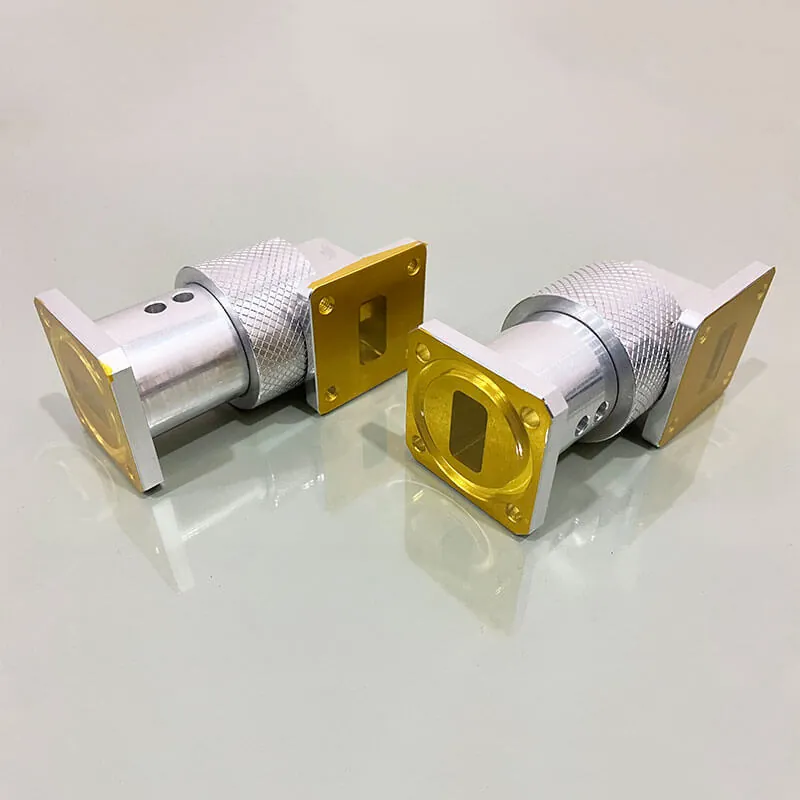
Connect the fixed feed line to a rotating antenna without twisting the waveguide. This WR75 model uses an L-style layout and covers the full 10.7–14.5 GHz band.
- Operating band
- 10.7–14.5 GHz
- Average power
- 750 W CW
- Insertion loss
- 0.2 dB max.
Before you order
Check the space around the rotating joint
Flange arrangement
The model drawing lists FBP120 cover and FBM120 grooved flanges. The L-style geometry has one arm perpendicular to the rotation axis.
Rotation and loading
The PDF lists 150/100 rpm and maximum interface loads of ±15 N in the axial and radial directions. Include the intended rotation duty with your enquiry.
Outdoor conditions
The listed temperature range is −40°C to +71°C, with 95% RH, 30 PSIG pressure and IP65 protection. Review these conditions together for your installation.
For the mating interface, check the EIA and IEC flange reference. If the feed line needs bending as well as rotation, the flexible waveguide selection guide explains which dimensions to specify.
For the rest of your setup
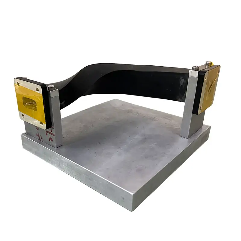
Does the fixed feed need a flexible section?
A flexible section can help route the stationary side of the assembly. It does not replace the rotary joint. Choose its WR size, flange ends and installed length separately.
Compare flexible waveguide assembliesTechnical data
Specifications & dimensions
Swipe or scroll across the table to see all columns.
| Model | DH-120WHPRJL10.7T14.5PMA750 |
|---|---|
| Frequency Range | 10.7-14.5 GHz |
| Operating Bandwidth | Full bandwidth |
| VSWR (Max) | 1.2:1 |
| VSWR WOW | 0.05 |
| Insertion Loss (Max) | 0.2 dB |
| Insertion loss WOW | 0.1 dB |
| Peak Power | 5 KW |
| Average Power | 750 W, CW |
| Phase variation over rotation | ±1° |
|---|---|
| Rotating speed | 150/100 rpm |
| Torque (min/max) | 0.20 Nm (@ 60°C) / 0.25 Nm (@ 20°C) / 1.5 Nm (@ -30 °C) @ start-up; 0.15 Nm (@ 60°C) / 0.20 Nm (@ 20°C) / 1.0 Nm (@ -30 °C) @ rotation |
| Interface loads, max. | ±15 N in axial direction; ±15 N in radial direction |
| Life | 20*106 revolutions |
| Waveguide Type | WR75 |
| Style | L style |
| Flange | FBP120 (Cover)/ FBM120 (Grooved) |
| Material | Al |
| Inside Finish | Chromate conversion coat per MIL-DTL-5541 type 1 or type 2 |
| Outside Finish | No Paint |
| Temperature Range | -40°C ~ +71°C |
| Humidity | 95% RH |
| Pressure | 30 PSIG |
| Leakage Rate | 10 cm3/min |
| IP Protection Level | IP65 |
| Weight, approx.. | 0.23 kg |
Materials & ordering options
Technical documents
Questions before ordering
Is 5 kW a continuous-power rating?
No. The specified peak power is 5 kW; average continuous-wave power is 750 W. Include pulse width and duty cycle if the signal is pulsed.
Can I order an I-style or U-style joint?
This listed model is L style. For another geometry, send a drawing showing the rotation axis and flange directions so the required configuration can be checked.
Related products

WR75 Waveguide Bandpass Filter
View productFor a WR75 signal path that also needs bandpass filtering.

Seamless Flexible WG
View productFor flexible routing on the stationary side of the assembly.

Waveguide Flange Standard EIA & IEC
View productTo identify the cover and grooved mating interfaces.
Tell us what you need
Have a model or drawing?
Send the operating band, average and peak power, rotation duty and flange drawing. Include quantity and the space available around the joint.




