The feeding structure of an antenna includes the feed point, feed line, balun, matching network, and feed array, optimizing signal transmission.
Table of Contents
Feed Point
The feed point is a critical location on an antenna, where the transmission line is connected to its elements. It is highly relevant due to the influence of this connection on the antenna’s performance and affecting its ability to transmit or receive radio frequencies efficiently. In a broader sense, selecting the correct location for placing an antenna’s feed point relates to many elements of the installation, such as signal strength, bandwidth, and others. For instance, in a simple setup, an average residential user could use a simple dipole antenna – a standard one used to pick up over-the-air television using a pair of parallel rods .
If one were to measure the center of this “pole” or dipole and connect a coaxial cable, one would achieve a balance. If the feed point were to be off-centered, one would not. In this instance, the dipole’s feed point would be at the center of its topology by attaching coaxial cable to the exact point where the pole or dipole’s two equivalent sides would meet . The lack of balance in the antenna’s feed points might cause the signal received to be imbalanced, affecting the quality of the overall reception. In addition, the impedance between the signal and the feeder network must be balanced, or in other words, a 75-ohm common coaxial cable should not operate with a 300-ohm dipole antenna. This imbalance might contribute to enhanced wave reflection, leading to signal losses of up to 4%-10% reflected back towards the source and not utilized .
The use of an appropriate balun allows the correction of these imbalances, converting the feeder network’s imbalanced signal into a balanced one to improve the performance of the entire system. Keeping the signal integrity improves the overall system’s longevity, limiting the wear-and-tear incurred by the receiver due to the stress generated by the traveling standing waves. Finally, the material does present an impact on the overall quality, with higher-conductivity materials such as copper or aluminum providing better performance. Their use also results in their lower resistance manifesting less lost energy in the form of heat and greater loss towards signal emission, improving efficiency. The price of the material in turn affects the long-term value of operation for both the longevity of the equipment and the power expenses.
Feed Line
The feed line is the tightly packed path that allows radio frequency power to flow from a transmitter to an antenna or a receiver and vice versa. This component is crucial in that it ensures that the RF energy can be transferred while keeping loss at a minimum.
In the context of a home Wi-Fi platform that uses either coaxial cables or twisted pair but the performance of the entire network is affected. Unshielded twisted pair might be at breast with RG-6 coaxial cables in terms of performance, but the signal is still weak and noisy over long distances. Setting up a router on the other side of the house would mean that the feed line is extended long enough for the RG-6 coaxial cable to lose signal strength as little as 1 dB per 10 feet away at 2.4 GHz a common Wi-Fi frequency. Unshielded twisted pair, under these same conditions, would deliver extraordinary losses of 3 dB per 10 feet. Not only does a feed line determine the signal quality, but it also determines the workability of the whole setup cost-effectively. To save on energy costs and signal amplifier purchases that would otherwise be driven due to signal loss, high-quality coaxial cables might cost as much as 20% extra than standard cables. The upshot is that the cables are only as expensive as less-than-ideal coaxial and still significantly cheaper than radios running on silvers.
In ham radio, getting the station up and running requires some degree of field line selection. In this case, the objective of a feed line selection is to find the best transmission range option for the power output limitation. A perfect length will allow the antenna to able to radiate the equivalent of all the power it receives as EPR or effectively radiated power. In the long run, the decision to use a feed line will determine whether a transmission can be made over a spectrum of hundreds or several thousands of miles on a good day.iforn
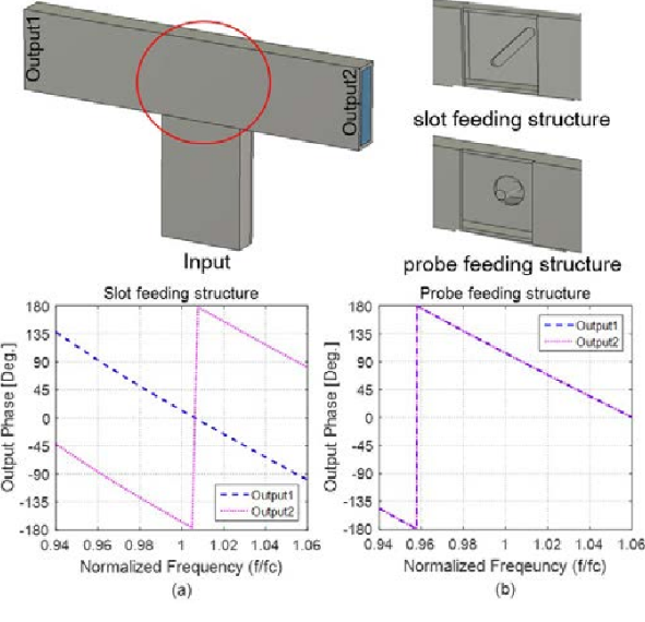
Balun (Balanced to Unbalanced Transformer)
Balun, a short for ‘balanced to unbalanced transformer’, is used to connect balanced antenna systems to unbalanced feed lines. In this case, it provides the necessary impedance matching and allows for effective signal transmission, optimizing the whole system. For example, in the context of a home television antenna, using a balun can have a considerable impact. Usually, a dipole antenna may have an impedance of 300 ohms. If a balun is not used, and the antenna is directly connected to a 75-ohm coaxial cable, 50 of the signal power would be lost as it travels back to the emitter after meeting the high-impedance cable. In this case, a balun turns the cable into an effective 300-ohm feed line, and the losses decrease to about 5% .
This has an immediate effect on the received quality of the signal, reducing interference, and making receiving the programs more stable and easy. Similarly, in ham radio, where ensuring range and clarity of the transmission is a high priority, a balun is used to make sure that the power the transmitter provides is not reflected back, but is successfully transmitted to the receiver. A 1:1 balun used in an amateur setup has the benefit of keeping SWR more or less flat across a wide frequency band for optimal use of available power and range of communication. Some baluns are more expensive, others are cheaper, meaning some applications are more cost-effective. For example, a good standard ferrite core balun suitable for low power would cost about $20. An even more wideband balun suitable for up to 1500 watts of transmission power may cost about $100. They also protect the equipment long-term from electrical imbalances.
Matching Network
A matching network serves to represent a combination of electric components, frequently capacitors, and inductors, that allow the antenna’s impedance to comply with that of the transmission line . The purpose of a match is to maximize the power coming from the transmitter and going towards the antenna while minimizing the reflections . In an amateur radio application, the matching network is a critical part of the setup, allowing the radio operator to gain the necessary power for his or her application.
For instance, if a ham radio operator wishes to transmit over several bands using a single antenna, this frequency range will change the impedance of the spectrum of the antenna dramatically. By using a matching network, the ham radio operator will adjust the impedance seen by the transmitter to maintain 50 ohms impedance, which is the standard impedance for radio gear. In turn, it will be easier to transfer the power from the transmitter to the antenna, as the input-output mismatch loss, which could have reached 30% without the circuit, will be cut to less than 5% with a matching system . The system’s efficiency will also grow due to the matching network’s higher power capability; for example, with the absence of mismatches, the power put through the cutting edge of the transmission box will double in a matched case.
Further, matching the network will better the functioning of the system as a whole, particularly as it will develop the frequency band of the antenna. As a result, in the case of scalable networks, such as tunable LC , users are allowed to modify their antennas’ systems according to the changes in the operational processes.
In terms of value, a percent network can be developed with purchasers’ parts worth up to $50. Otherwise, more sophisticated summoners that stand higher voltage withstand and manage hundreds of frequencies will amount to a few hundred dollars. It is possible to suggest such an investment is worthwhile, as it will result in higher signal potency and quality, which is especially crucial for intercontinental communication.
The vital aspect of constructing the matched network is the development of a matching network that will remain stable under the difficult circumstances of the operational stress of high temperatures and voltage. The use of quality capacitors and inductors that will not crack is vital for facilitating steady transmission and the resulting decrease in the costs associated with maintenance replacement or radio service interruptions.
Feed Array
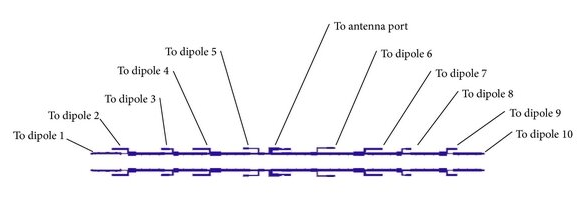
A feed array is a complex system of feeding antennas, which is used in the design of the antenna where many antenna elements must be fed with signals with a specific feed to form a specified directional pattern. It allows the phase and amplitude of the signal to the antenna to be controlled precisely, and thus leads to a high directivity and therefore a high gain of the antenna. In practice, like radar systems and satellite communication arrays, the feed array is widely used. In case of a phased array radar, the phase of the signal fed to each element of the antenna is dynamically changed. Using this property, a beam can be formed that can be rapidly directed to the desired angle, and the antenna need not be moved mechanically. The use of a feed array reduces the response time from seconds to a few milliseconds .
The power-handling is determined by the power-handling capabilities of the feed array. One advantage of using a feed array in a weather radar system is that each antenna element receives the same power as the rest of the antenna system. Since the feed array is broadband, there is no restriction on other than reduced power handling capacity. In a feed array used for broadcasting, the power to the feed is often in the kilowatt range as opposed to the watts typically used for other applications. The use of a feed array allows power to be fed in batches, which is especially important for maintaining a stable and uniform signal in a broadcast. Also, the absence of power loss in the feed array means that no part of the antenna is exposed to heat and the problems that can result from it.
The manufacturing, as well as the installation costs of the feed array, can be quite high. For large feed arrays, costs may seem fairly high, and several thousand dollars may need to be allocated for the installation. The high costs of the equipment and the system can be a disadvantage. However, in the long term, the low need for physical decay and the long period of time to be benefited from it can offset this disadvantage. Some factors related to the materials used in a feed array system are as follows: The use of cables, connectors, and other components made of low-loss substances in order to reduce power loss, which is essential . The durability of the components, which should resist the effects of different climatic conditions and withstand large electrical loads, should require less repairs and less costs for re-installation to ensure a long lifetime in the system.

