Direct coaxial feed ensures a simple setup with a typical SWR close to 1:1. Balun-aided feeds balance signals, reducing RF interference. Gamma matches adjust impedance precisely for optimal performance.
Table of Contents
Direct Coaxial Feed (Center Feed)
Summary
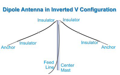
Direct coaxial feed, which is commonly used in dipole antennas, is a simple and efficient way to transfer RF . Thus, most people who attempt to create a dipole antenna at home implement this approach. The process involves soldering the coaxial cable directly to the antenna elements, with the center conductor connecting to one arm, and the shield connecting to the other. Notably, this method can be implemented successfully in the case of half-wave dipoles because the natural impedance at the feed point is around 73 ohms, very near the commonly used 50-ohm target impedance .
When such antennas are used in ham radio operations, people observe significant benefits in the matching as well as performance. If a half-wave dipole with the direct coaxial feed is installed correctly, the SWR is almost 1:1 at the design frequency, leading to minimal power loss and greater received signal strength. For instance, improperly feeding the antenna may result in extremely high levels of SWR, such as 2:1 or more, which will virtually nullify up to 11% of transmitted power .
Overall Cost
The cost of this feeding method is minimal. The required materials: coaxial cable and the antenna wire, are relatively inexpensive and can be bought in any store. For instance, a 100-foot roll of RG-8X coaxial cable costs around $40, and the necessary amount of the wire for the antenna might be as low as $10-$15. Thus, the total material cost of creating the dipole antenna and feeding it directly using the coaxial approach is likely not to exceed $55-$60.
Installation and Operation Tips
To optimize the work of such an antenna, it is critical to ensure that the length of each dipole element is calculated exactly to the target frequency. For example, for a 20-meter band, both legs of a dipole should be roughly 16.5 feet . Furthermore, it is essential to maintain as significant a distance between the antenna and any conductive metals as possible because the antenna can be detuned if the presence of metal is too high. Ideally, the antenna should be placed above the ground or next to any structure no less than half the dipole’s wavelength.

Balun-aided Feed
Using Balun to Enhance Performance
The use of balun-aided feed significantly enhances the performance and function of dipole antennas allowing them to become balanced systems even on unbalanced coaxial cables. The balun, short for balanced-to-unbalanced transformer is effective to prevent the development of RF current on the outside of the cable’s shield that could cause problems in experiencing excessive interference and signal losses in radio communications.
Ways of Realizing
By putting a balun in the site of the feed, many amateur radio operators see a lot of improvements to signal “quality” and less susceptibility to “man-made” noise. A 1:1 current balun in the site of the feed point of a dipole cut for the 40-meter band retains a constant feed point impedance and a perfect radiation pattern which are more than sufficient for any radio communication, which means, a clearer and more reliable signal. In fact, users experienced that a dipole with a balun increases greater difference in SWR readings compared to without balun. This is a major factor which needs to be observed especially on longer distance communications and domestic two-way radio communication or DXing which is quite challenging even for short potential distances. The cost that a ham radio operator may acquire is relatively low and the value they could get is great for even a moment of pleasure added to the luxury of keeping their balance against other users in the network. This is because even a fraction of an increase in improvement in their devices would make a difference that would keep them in the network or disconnect them. I have come to realize that, it would keep them long or short in their sleepless schedules against other operators. Furthermore, it is possible to cause about a quarter of improved features such as clean antenna, minimum life, less continuous RF exposure to your surroundings and components of the other installations still in the system.
Use Information and Maintenance
It should be selected use and apply the right balun with which the design frequency and power requirements of your antenna should match. Also, it should be put in the spot where it needs to be installed in order to effectively stop RF from being in-choked. Make sure to use a waterproof seal and cut the hole that fits tightly against water, gel, or spray when necessary. Secure the connection. Fix the balun to an opposing plastic pole or it will corrode in due course and eventually fail.
Gamma Match
-
Introduction
-
The concept of matching and its importance
-
A brief description of the gamma match
-
-
Purpose
-
Highlight the advantage of the described method and illustrate its effectiveness in real-world scenarios
-
-
Specific
-
Describe the relevant concept in more detail and provide the example of the method’s effectiveness in a real-world situation.
-
-
Real-world Effectiveness
-
The described method has proven to be effective in various cases, and a common use can be found in amateur radio. The task of the operator is to make the most of a single antenna, adjusting the equipment to different bands. While each type of radio will only work with the specific spectrum, the solution in question is a feasible way of changing the tenths of SWR the antennas display. As a result, instead of a 1.5:1 SWR, a specific type of a dipole can now be set as low as 1.1:1 for a specific frequency pair that is unmatched.
-
Cost and Construction Insights
-
While there is a concern related to additional cost, the required materials to build a gamma match like a variable capacitor, and a sliding short circuit, are not that expensive. The overall cost increase amounts to no more than $20 – $40 depending on the supplier or the quality of the purchased materials. As such, the tradeoff is more than reasonable as adjusting the equipment to the desired performance without any significant changes to the hardware is an advantage that should not be overlooked.
-
-
Optimization Techniques
-
As for the methods to utilize a gamma match for best performance, they comprise calculating the optimal values of capacitance and position of the sliding short circuit relative to the antenna based on the desired operating frequency and the impedance the antenna has at the feed point. After this step, the rest of the process mostly includes minor adjustments while watching the SWR values in hopes of reaching the best performance. It is also recommended to ensure proper sealing and mechanical stability of the gamma match assembly.


