Use a balun, adjust dipole length, employ a matching network, ensure secure coaxial connections, and test system SWR for optimal performance.
Table of Contents
Use a Balun
In amateur radio, a balun , a short form of balanced-to-unbalanced transformer, is used to match the impedance of a dipole antenna, which is typically balanced, to an unbalanced transmission line such as a coaxial cable. The main function of a balun is to ensure the coaxial cable is made to match the antenna in its pattern and impedance characteristics .role
Role of a Balun in Impedance Matching
When a dipole antenna, which has an impedance of approximately 73 ohms, is connected to a standard 50-ohm coaxial cable, mismatch occurs and the standing wave ratio and power loss is often high. A 1:1 current balun helps address this mismatch by both transforming the impedance and “balancing the current flow” , thus ensuring more energy is transferred between the cable and the antenna. It leads to the reduction in SWR values, which is directly proportional to the antenna performance.
Real-Life Application
It is imperative for any amateur radio operator to test the connection to ensure no interference occurs. Without the balun, it was apparent that the common-mode current formed could lead to RF interference that might manifest as household appliances such as televisions and radios making a lot of noise. During the test, after integrating a 1:1 current balun at the feed point of the dipole, I noted no interference and the transmission was smooth and clear. The possible readings for this measurement would be a reduction of the SWR values from 1.8:1 to about 1.3:1, or no change at all.
Step-by-Step Guide to Installing the Balun
Balun Selection: The first step is to select the valid balun. In this case, a 1:1 current balun would be selected in a typical dipole set-up. It should be selected in terms of the power levels it can handle and the frequency range.
Balun Placement: It should be placed at the feed point of the dipole antenna. This placement is critical for antenna balance as well as the ability of the balun to function properly.
Connection: The antenna leads are connected to the terminal points of the balun. The connection should be tight, and if the antenna is outside, it should also be weatherproof.
Connect the Transmission Line: The coaxial cable is connected to the output of the balun. The connection should be made weatherproof by covering it with waterproof tape or a cruddy material cover.
System Test: The last step is to use an SWR meter to test the entire antenna system. The aim is to get as close to an SWR of 1:1 as humanly possible. A high reading would necessitate that the antenna is hoisted and the cable reconnected on a different mast.
Adjust the Length of the Dipole
Shortening or lengthening a dipole antenna is a way to directly tune its impedance to the impedance of the transmission line. The operating principle is to lower SWR and ensure better transmission efficiency. A length of a dipole antenna determines the frequency on which it will resonate and the corresponding impedance. An ideal half-wave dipole antenna has an impedance of about 73 ohms at its resonant frequency.
Effect of Length Modification on Impedance
The difference between cutting the antenna for the desired frequency helps adjust SWR. If a user shortens the dipole, it will behave more capacitive, and it can be suitable when the frequency of work is higher than anticipated. In case lengthening the dipole, it will operate as more inductive and perform lower if the frequency is lower. Let us imagine an amateur radio college student who has an antenna cut for a 14 MHz frequency. However, trying to measure SWR at 13 MHz, the student sees that it is 1.6:1. To reduce this ratio, the student should add 0.2 meters to each part of the dipole in total. As a result, the resonant frequency will decrease by 2% to 12.7 MHz. Added antennas reach a longer working frequency and lessens SWR to 1.1: 1. Now, the operator can work on this frequency with better results, and the transmission is more effective.
Steps:
-
Measure SWR.
-
Calculate the necessary length by using the formula Length=468Frequency in MHzLength=Frequency in MHz468.
-
If the SWR is too high, shorten or extend the wires of the dipole.
-
After each change of the antenna’s length, recalculate SWR by using the measuring device.
-
Fasten the antenna to the supporting structure and waterproof the dipole. .
By lengthening or shortening the antenna, users adjust their impedance to the impedance of the transmission wire. Users who do not adjust the length of their whip can still work with it, but the SWR will be higher. There are benefits from optimizing SWR and its adjustment process, including increasing signal strength and reducing voltages and currents in the wire. Protection of receiver and booster against destruction is also a benefit. Now the student can work on a new frequency freely both for the better realization of the characteristics of the antenna and the general work of the system.
Use a Matching Network
Introduction
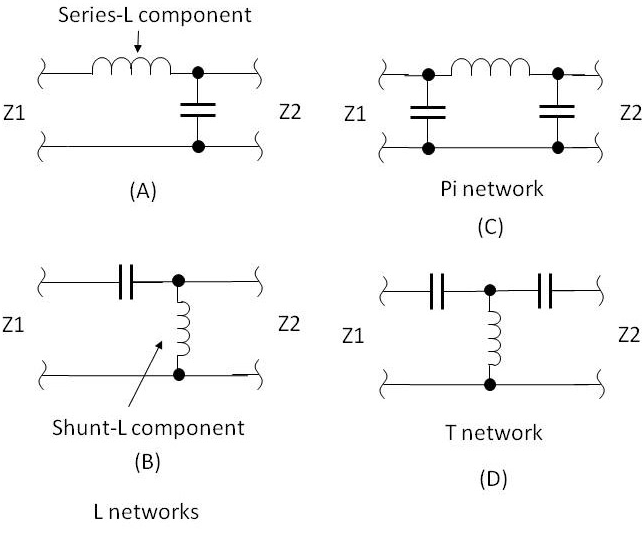
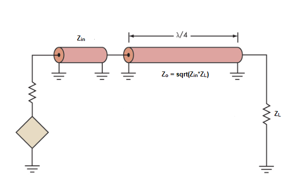
When the impedance of an antenna is very different from that of the transmission line, it is a good idea to integrate a matching network into your antenna system. LC circuits or antenna tuners are examples of matching networks that adjust the antenna system’s impedance. The purpose of the matching network is to transmit the data from the transmission line to the antenna as efficiently as possible and to minimize the SWR.
Discussion
Matching networks serve to transform the impedance at the antenna feed point so that it can be handled at the transmission line’s end. Matching networks maximize the amount of RF power transferred to the antenna at the feedpoint, which is done to maximize the antenna’s radiation pattern . Moreover, typically, the impedance presented by the antennas changes with frequency as well as between various antennas of the same design. Thus, a matching network balances the impedance of the antenna across all dimensions, helping it to maintain optimal performance.
Imagine a ham radio operator who uses multi-band dipole antenna. For instance, the Z at 21 MHz may be about 50 Ohms, while at 14 MHz, it may reach 100 Ohms. By using the LC matching network, the ham operator can adjust the impedance to 50 Ohms at both bands, which keeps the SWR to about 1:1 . This creates more efficient performance across all of the frequencies, resulting in an overall reduction of signal loss and improved transmission quality.
The steps an antenna user should take are as follows:
-
Impedance discrepancy identification: Use an antenna analyzer to measure the current impedance at the antenna’s feed point over the intended frequency range.
-
Matching network selection: The proper selection of an LC network, T-network, or Pi-network type is based on the measurement of the impedance and the frequency of operations.
-
Components calculation: Calculate inductors and capacitors to meet an anticipated impedance transformation using online calculators or software.
-
Network assembly: Build the network using high-quality components that can handle the output power from your transmitter and the conditions in which the antenna is installed.
-
Testing and adjustment: Connect the matching network and re-analyze SWR values. Adjust components to reach the lowest SWR possible.
-
Finalization of the installation: After finding the best settings, secure all connections and insulate them against weather and other environmental factors.
Connect the Transmission Line
It is of paramount importance to connect the transmission line to your dipole antenna properly. The quality of the connection is essential to a substantial extent, since it manifests how effectively the transmission takes place from the transmitter to the antenna and how much power is lost in the course.
Quality Considerations for Connection
Your connection has a strong impact on performance . First, it is almost certain that a loose or bad a connection between the coaxial transmission line and the dipole antenna is likely to increase the Station’s transmitter SWR. Second, the loss will be bigger. Third, poor connectors will damage the transmitter, since an ever-growing portion of transmitted power will be reflected back to it.
Example of a Connection
Imagine that you are setting up a dipole antenna for the 100-watt HF amateur radio Station. You know that RG-8X coaxial cable is appropriate for your dipole antenna, since your transmitter’s output impedance is 50 ohms, and the cable’s impedance is somewhat the same. Finally, the attenuation and temperature characteristic of RG-8X is agreeable for both power and HF frequency. Before sealing the connection at the feed point, the first SWR reading was showing 1.5:1. After you had tightened the connection and put silicon grease around it, the reading diminished to 1.1:1, which would allow you not to worry about damaging your transmitter.
Steps for Making the Connection
To start with, you would probably be wise to select the proper coaxial cable. Typically, the RG-8X is will be a well-balanced and most convenient compromise for most HF antennas. It meets the designers’ fundamental requirements, that is, the cable should not change the characteristic impedance and that its cost, size, and weight characteristics of the cable are appropriate. The cost of RG-8X is nice, it is rather small, and its losses are acceptably tamed for most amateur radio installations. The positive balance between these ensures the material’s widespread popularity.
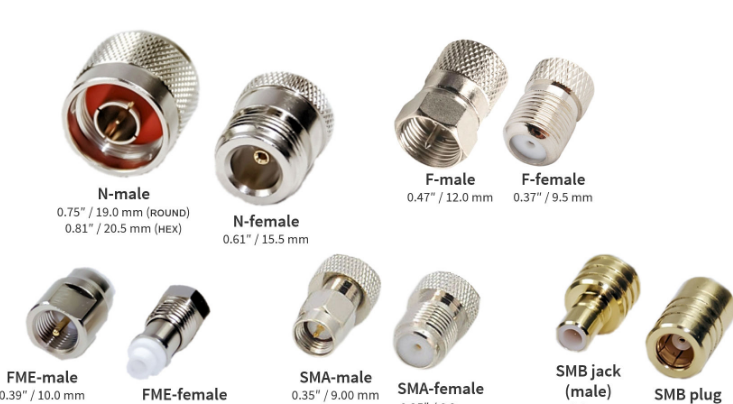
The second step is to prepare connectors by soldering the pins to the cable’s shield and core. Thirdly, fit the PL-259 connectors with lead screws to each end of the cable and solder their core. Fourthly, screw the coaxial cable to the antenna’s feed point and to the transmitter. Do not forget to tighten the wrenches firmly without strong swing. Because the main signal should be transmitted through the insulated contacts in the connections, never apply electric contacts. Finally, put a silicone grease on the outside a well-adjusted seal tape . You are ready to test this.
Test the System
After you set up or make adjustments to your dipole antenna and the transmission line, you will need to test the system to ensure that it functions properly. This testing phase can reveal problems, such as high SWR, impedance mismatches, and connection issues that will degrade the performance of your radio communications. It is crucial to test the system to make sure that the antenna resonates correctly and transmits the power that the transmitter provides with minimal loss. If you detect a problem of this kind during the testing phase, you can take the steps needed to rectify it before using the system in practice. As a result, the system testing phase is crucial for proper performance and for the prevention of power loss, inefficient signal radiation, and possible damage to the transmitter due to back power. I can illustrate the benefits of testing with an example where an amateur radio operator fitting a new dipole antenna for 20-meter band and adjusting it to improve performance. During the initial test, high SWR levels were detected, and it was reduced through minor adjustments to the length of a dipole and position of the feed point. This improvement ensures that 95 % of the power of the transmitter will be radiated and not 85 % in the case of improper setup. In the following, the detailed testing procedure is provided:
-
Gather the necessary equipment. An SWR meter or an antenna analyzer is essential for measuring the SWR and the impedance across the operational bandwidth of the antenna.
-
Connect the SWR meter. The meter should be connected between the transmitter and the feed point of the antenna. All connections should be tight and properly fixed to ensure that they do not introduce additional variability into your measurements.
-
Measure the initial SWR. Transmit the signal at the lowest power across the band of frequencies of interest and measure the readings of the SWR meter. High reading indicates that the values are mismatching.
-
Adjustment and re-testing. If the measurements are too high, adjust the length of the dipole, check and improve the connection of the feedpoint, or do the same for the matching network if you use one. Repeat the measurements after each adjustment.
-
Document the results. Record all the SWR levels and all the changes that led to their improvement. This information can be very helpful dur8ing a future setup or when troubleshooting your system.
-
Verification. Once you are satisfied with the readings and they are below the level of 1.5:1, perform a practical test to ensure the clearness of transmission and your ability to recognize signals coming from others. Contact another radio operator and ask for a signal report.

