The impedance of dipole antennas is affected by length, height above ground, environmental factors, feed point position, and construction materials.
Table of Contents
Antenna Length and Frequency
One of the critical aspects of determining impedance for a dipped antenna in the context of radios is the ratio of it to the signal the device is intended to carry. Normally, dipped antennas are half the length of a whole-frequency relation to the signal they are meant to transpire. These factors are combined due to the antennas’ standard operation in the resonant signal, where their best effects are observed. The impedance of a dipped antenna that is breath or thickness is half of the frequent relation, the basic types of the cable used for the signal. Commonly, these are 50 ohms and 75 ohms.
Basic Principles
One of the immediate issues is correlative ratio frequency to signal the dipped antenna is intended to handle. Formed by its width, these nuclear objects are half of the frequency of the signal they are transferring due to the signal processes of the resonant.
Frequency from Signal and Relation with its Width
From classic physics, it is known that the frequency of the signal directly correlates with the length of the signal through the frequency formula, where λ=\frac{c}{f} . Assuming the frequency is 300 MHz, approximately one meter will be the length of the signal. In order to match this length, a 0.5m length will be made from the end to exposure by a half-wave from one side. The most recommended length is ~73 ohms, the most accepted, and still considered meanwhile in many odd cases to be transmitted.
Extension Applied to Real Life
For amateur radio, many amateurs, when broadcasting various bands, operate on the twentieth band, which has a relation to the 14 MHz signal intent. With that, the signal is approximately twenty meters, so its half-wave will be around ten meters. Using larger or shorter signals, the coverage area can be doubled or decreased, respectively. The most frequently used ratio of anode length is in the order of ten meters. Normally, those weekends, the operation can be over 3,000 miles, which is evidenced over the last week by the strong pennies of these areas. Impedance is 50 ohms, but you can zoom into 10.1 meters or 9.9 meters ago, resulting in 10-15 ohms gained.
Height Above Ground
The height at which a dipole antenna is mounted above the ground is an important aspect in determining its impedance. In the context of the given situation, the issue under discussion is relevant in that it is connected to the way a specific set-up of the transmission device could affect the overall performance. In general, installing a dipole antenna in proximity to the ground affects its impedance because the earth’s near-field impacts the radiation pattern. Consequently, its impact can vary from decreasing the impedance of the near-ground level set-ups or allowing them to perform with relatively minor impedance loss at half-wavelength of height and above.
If a dipole is installed very close to the ground such that it is 1/10th of a λ or less high above it, the impedance can decrease greatly . Usually, this decrease can be attributed to the capacitive impact of the ground by which capacitance to the set-up is added. In the case of a dipole that is designed for the 20-meter band and has the ideal impedance in free-space conditions of about 73 Ω, installing it on the ground that is only several feet away would result in the interaction between the elements and cause the impedance to fall below 50 Ω. As for the optimal level of performance, it is usually suggested that a dipole should be mounted such that it is at ½ λ height and above for minimum loss and maximum radiation . In the given situation, the most reasonable set-up would be that the dipole was to be located at 10 meters which is approximately 0.5 λ after enhancing its efficiency through moving it far above the ground. This alteration ensures that the impact of the ground is minimized both in terms of increased impedance back to free-space levels and reduced ground absorption.
In terms of materials and cost, it is vital that the antenna is made from materials of decent quality that would ensure that it remains in good working order for as long as possible. Therefore, in case of an aluminum dipole, the length of kept within an insulating PVC or fiberglass sleeve and mounted on a similar support, the cost could vary between 50 $ and 100 $ . For the given practical advice, I am an enthusiastic radio-amateur who resides in the problematic part of the city where it is unlawful to install large antennae or, sometimes, where there is simply not sufficient space to do so. In either case, a set-up of the higher-band, doublet type could be installed at 8 meters which would allow for decent impedance that would not transgress any legislation, while it would still remain somewhat flat for clear radiation pattern free from most obstructions like trees and neighboring buildings.
Antenna Environment
The impedance of a dipole antenna is highly affected by the environment due to the fact that such conditions as the glaciation of the supporting roles for the dipole and the presence of the earth affect the pattern of the electric field surrounding the dipole. The same radio pole mounted four meters above ground and, having a given radiation power pattern, supplies a given field above the earth. Hence, the environment significantly influences a dipole antenna’s impedance. Specifically, the impedance is mainly influenced by the surrounding medium that reflects, absorbs and transmits electromagnetic fields. For instance, the presence of nearby structures, such as buildings and trees, and other factors, such as soils and nevel towers, can decrease the impedance of the antenna severely. The most significant impact on the signal seems to be provided by the presence of large buildings, as they influence the signal’s phase and lead to possible cancellation of its parts. In my example, I assume that the dipole antenna is mounted close to a large metal building’s side. Hence, the impedance decreases and the radiation pattern is significantly attened, so the loss of signal is more intense.
The presence of trees in the radiating path of the waves also influences the antenna’s operation. Vegetation absorbs the wave rapidly, and the denser it is, the less powerful the signal will be. Specifically, the foliage absorbs the signal passing across it to the degree that it goes off. In my case, the dipole shines through the dense foliage, so the signal is absorbed rapidly, and most of it is eliminated. For frequencies 2.4 GHz and 150 MHz, the difference in signal feeding would be even more apparent. The dipole antenna should be positioned lower in order to avoid the foliage or moved to an area where more room is available. A better variant would be to cut some branches from the trees, but this interferes with nature and the antennas have to be temporary if they are installed for the purposes such as field meters in amateur radio.
The general cost of an antenna system installation might be quite high because no metallic conduction poles, for instance, could be used. It would cost over 1,000 dollars. In a rural area, however, the costs would be lower, as in a forest or a grass area poles could be used and the cost would be around 100 dollars.
Feed Point Position
You are dealing with a dipole antenna directly affects its impedance and overall effectiveness in radiating or receiving radio waves. Normally, it is fed at the center, which is practical to achieve a balanced impedance and an efficient radiation pattern.
Center vs. Off-Center Feeding
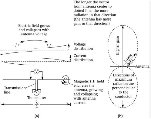
When fed at its center, the feeds point typically has the lowest voltage and maximum current along the antenna. As a result, the impedance should be nominally resistive at 73 ohms in free space. This facilitates matching it to common 50 or 75-ohm coaxial systems through baluns, which help transition from a balanced to an unbalanced configuration to ensure power transfer. This makes its efficiency in resonance the highest.
Off-center, the impedance changes greatly. For instance, placing the feed point towards one end increases the impedance on one side. Although this may be beneficial for applications involving very high impedance, it typically requires additional system components, making the overall antenna system less efficient.
Effectiveness in Different Scenarios
For example, by the use of an off-center fed dipole, an amateur may access a large swath of the spectrum without the need of a tuner. Here, the feed point is usually away from the center by a small portion, typically 1:3 from one of the center’s sides. This enables the target frequencies to be covered by selecting the appropriate length of wire until a proper impedance is reached over a narrow band to achieve flexibility. This can be used by amateurs to cover different bands that are open for propagation and decide the best band to make contacts.
Cost of Materials and Construction
For a basic center fed dipole and a balun, the cost is around $50 for the materials. On the other hand, more sophisticated off-center fed and expensive choke-based dips, as well as carefully designed impedance matching networks with Up-and-out phosphor bronze chokes can cost around 100 dollars for the same materials.
Time Consideration
Center-fed dipoles are relatively quickly built in less than an hour while maintaining the best configuration. Still, they require more preparation and planning due to the need to select the proper length, while also enabling testing and changing the connectors, if necessary. Antennas with off-center feeds require more time and effort to properly tune and test, which might take several hours.
Material and Construction
The materials used for building a dipole antenna and its overall build quality are some of the most critical factors that affect its impedance, performance, and durability. The right choice of material will determine the antenna’s capacity to conduct the electric current effectively and resist environmental and physical stresses. There are two important points to discuss in this context: the preferred material to use for the antenna and the quality of this material. Both points will interact with each other to impact such parameters of the antenna as its impedance, resistance, efficiency, durability, and value.
Choice of Conducting Material
Copper is the most common material used for dipole antennas because it is highly conductive electrically and durable . A copper wire antenna offers the least resistance to the RF current possible and is also capable of supporting the widest bandwidth of all materials that are usually used to construct antennas. Aluminum, while less expensive, lighter, and easier to handle than copper, would have slightly more resistance and be more vulnerable to corrosion if not coated correctly. The difference in cost is worth noting: the copper wire will likely cost around $0.10 per foot, whereas the equivalent aluminum wire costs approximately $0.05 per foot.
Implications of Material Quality for Antenna Performance
The quality of the material also affects the antenna’s efficiency by determining the level of resistance. The better-quality materials will feature lower resistivity, or the metal is less conductive. In other words, the better quality materials experience fewer resistive losses, which enable more efficient transfer of power from the transmitter to the antenna and back . For example, an antenna built with high grade of copper, such as the high purity copper with specifications for use in electrical applications, would have an efficiency rating of nearly 90%. The efficiency of 75% would be significantly lower, however, for an antenna constructed with a lower grade copper or poorly coated aluminum.
Durability and Material Resistance
The resistance and durability of the material will also affect the lifespan of the antenna because they will determine how well the antenna supports itself under weather and time-related stress. The mounting hardware and balun could be made of stainless steel because of its strength and rust-proof qualities . The major drawback here would be the increase in price: while the conventional wire and PVC insulator antenna would cost about $50 total, the total price of the stainless steel hardware, and the balun would be about $20-30 higher. However, since the antenna lasts much longer and does not need such consistent maintenance, it should be a much better purchase in the long run.


