default

5 working principles of waveguide display

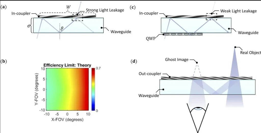
Waveguide displays use ​​total internal reflection​​ (TIR at ​​>41° critical angle​​) to guide light through ​​high-index glass (n=1.8–2.0)​​. ​​Diffractive gratings​​ (300–500nm pitch) couple RGB light into the waveguide with ​​<5% efficiency loss​​. ​​Pancake optics​​ fold the optical path, enabling ​​60° FoV in 5mm-thick guides​​, while ​​nanostructured metasurfaces​​ enhance brightness by ​​200cd/m²​​. ​​Eye tracking​​ (90Hz update) […]

5 working principles of waveguide display Read More »
3 modes of transmission of waveguide

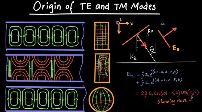
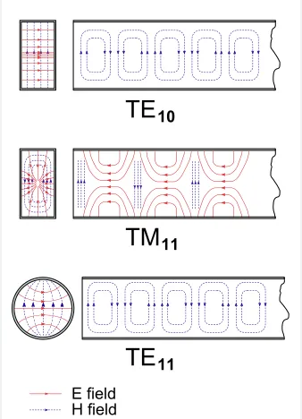
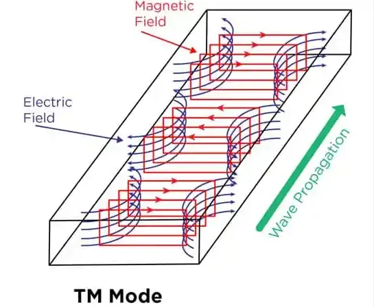
Waveguides transmit signals via ​​TE (Transverse Electric) modes​​ (e.g., TE10 dominant in WR-90), ​​TM (Transverse Magnetic) modes​​ (like TM11 with ​​cutoff frequency 6.56GHz​​), and ​​hybrid modes​​ (combining E/H fields). ​​TE10 operates at 8.2–12.4GHz​​ with ​​lowest attenuation (0.1dB/m)​​, while higher-order modes (TE20/TM11) cause ​​dispersion losses >3dB/m​​. Precision ​​machined flanges​​ maintain ​​VSWR <1.1​​ by suppressing unwanted modes.

3 modes of transmission of waveguide Read More »

5 key points to improve antenna efficiency

Optimize impedance matching (VSWR <1.5:1) using a vector network analyzer, select low-loss materials (dielectric constant ε<3) to minimize dissipation, and position radiators λ/4 from ground planes to reduce cancellation. Fine-tune element lengths (±2% of λ) via HFSS simulation, and minimize feedline losses with LMR-400 coax (0.14dB/m at 2GHz). Ensure proper polarization alignment (cross-pol <−20dB) and

5 key points to improve antenna efficiency Read More »

6 reasons TEM mode cannot exist in parallel planar waveguides

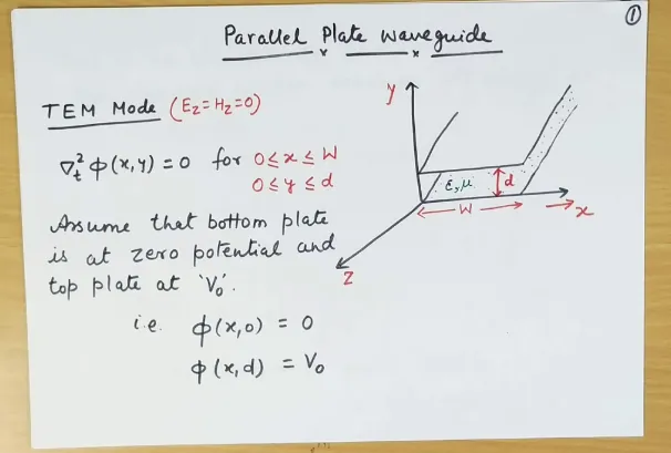
TEM mode requires two conductors with independent E/H fields, but parallel plates lack a closed current path, forcing quasi-TEM (fringing fields). Cutoff frequency limitations (fc=0 for TEM) conflict with waveguide dispersion, while boundary conditions only support TM/TE modes (m,n≥1). Field solutions demand non-zero kz, impossible with TEM’s transverse-only propagation. Single-conductor confinement prevents static-like field distribution,

6 reasons TEM mode cannot exist in parallel planar waveguides Read More »

6 Reasons TM01 and TM10 Modes Can’t Exist in Rectangular Waveguides

TM01/TM10 modes cannot exist in rectangular waveguides because their field equations require zero longitudinal electric field (Ez=0) at all boundaries, which is impossible given the waveguide’s width (a) and height (b) dimensions. The Helmholtz equation solutions demand m,n≥1 for TM modes, making TM00 mathematically invalid. Cutoff frequencies (fc= c/2√[(m/a)²+(n/b)²]) become undefined when m or n=0,

6 Reasons TM01 and TM10 Modes Can’t Exist in Rectangular Waveguides Read More »

6 meanings of Te and TM in rectangular waveguide

In rectangular waveguides, TE (Transverse Electric) modes have Ez=0 with non-zero Hz (e.g., TE10 dominant mode at cutoff frequency fc= c/2a), while TM (Transverse Magnetic) modes have Hz=0 with non-zero Ez (like TM11 requiring a=b for propagation). TE modes exhibit electric field purely transverse to propagation, with magnetic field having longitudinal components, whereas TM modes

6 meanings of Te and TM in rectangular waveguide Read More »

6 differences between MIMO and array antenna

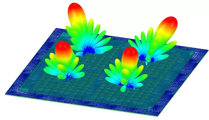
MIMO antennas use multiple independent data streams (2×2 to 8×8 configurations) for spatial multiplexing, while array antennas combine signals coherently (4-64 elements) for beamforming. MIMO operates at 2-6GHz with 20-100MHz bandwidth, whereas arrays achieve 30° electronic steering at mmWave (28/39GHz). MIMO improves capacity (4x throughput), arrays boost gain (20-30dBi). MIMO needs rich scattering, arrays require

6 differences between MIMO and array antenna Read More »

5 reasons why corrugated horn antennas are more efficient than conventional horn antennas

Corrugated horn antennas achieve 20-30dB side lobe suppression and 98% aperture efficiency versus 50-60% in conventional horns. Their grooved inner walls (λ/4 depth) enable hybrid mode operation, reducing spillover loss by 3-5dB across 1.5:1 bandwidths. The corrugations create symmetrical E/H-plane patterns (±0.5dB variation) ideal for satellite feeds, outperforming smooth-wall horns’ 10-15dB cross-polarization levels at 10-30GHz

5 reasons why corrugated horn antennas are more efficient than conventional horn antennas Read More »

5 kinds of satellite communication antennas

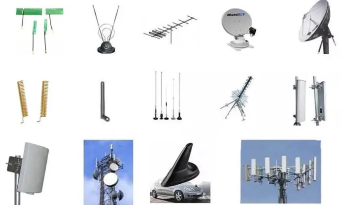
Satellite communication antennas include parabolic dishes (1-10m diameter for 2-30GHz signals), phased arrays (electronically steerable with 100+ elements), helical antennas (3-30dB gain for L/S-band), patch antennas (compact 2-6GHz for LEO satellites), and horn antennas (15-25dBi gain for ground station feeds). Each type offers distinct frequency coverage (UHF to Ka-band), polarization (linear/circular), and tracking capabilities for

5 kinds of satellite communication antennas Read More »

Scroll to Top
Blank Form (#3)