default

Q-Band, 33 – 50 GHz, 2/4-Way Power Divider/Combiner, Isolation 20 dB, Insertion Loss 0.3dB

Q-Band, 33 – 50 GHz, 2/4-Way Power Divider/Combiner, Isolation 20 dB, Insertion Loss 0.3dB

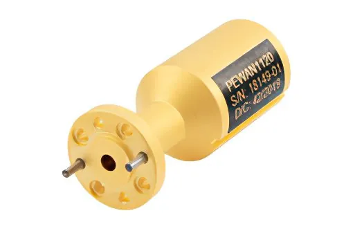
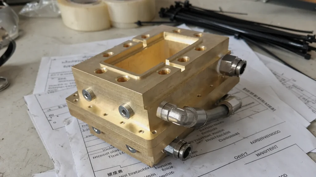
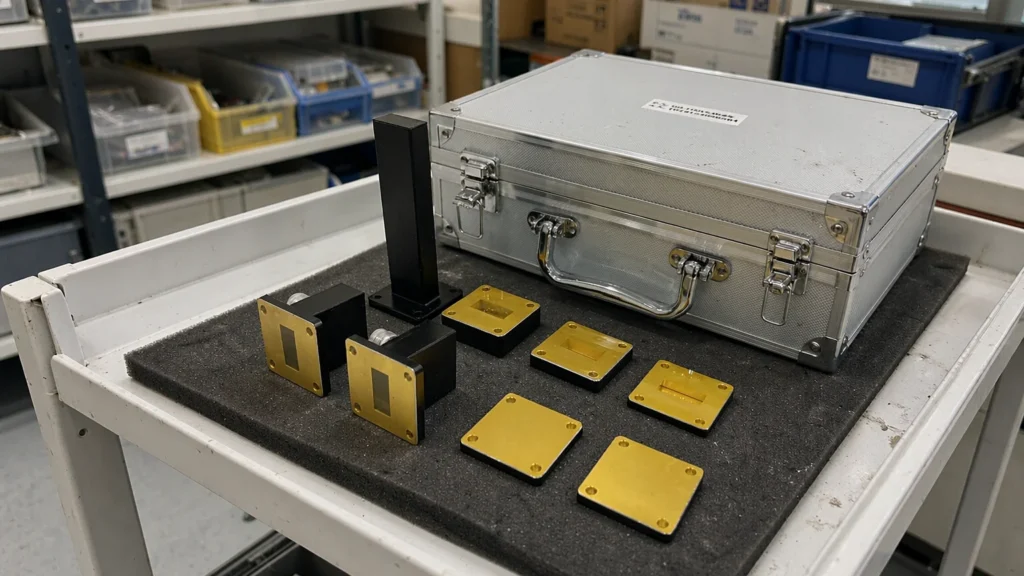
Dolph Microwave’s 2/4-way power divider/combiner the input signal into four output signals with minimal loss. 4-way power splitters are widely used in wireless systems to evenly distribute power throughout the entire system. These allocators provide well balanced ports and can be used for in-phase power division or combination. DH-400WCDW31_ 4PC is a full band WR-22 […]
Q-Band, 33 – 50 GHz, 2/4-Way Power Divider/Combiner, Isolation 20 dB, Insertion Loss 0.3dB Read More »

4.64-7.05GHz, Waveguide High Power Termination 750W.

4.64-7.05GHz, Waveguide High Power Termination 750W.

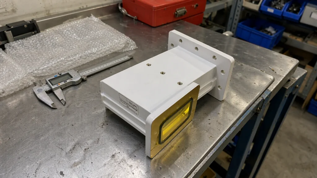
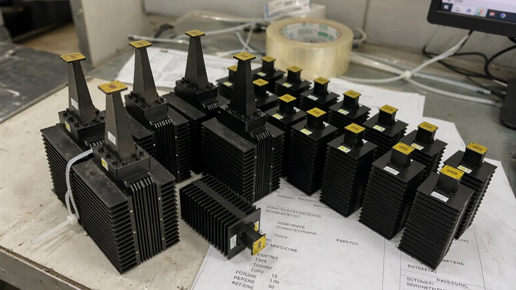
Dolph Waveguide high power termination is manufactured by casting with fins. The special heat-resistant absorbing material and heat emission mechanical design improve the overall capability. Dolph Microwave rectangular and double ridge waveguide termination models frequency are covering from 1.10 GHz to 50GHz, Features with high stability, good accuracy and fast response. The termination loads offer

4.64-7.05GHz, Waveguide High Power Termination 750W. Read More »

Millimeter Wave Products Processing by Dolph-Microwave

Millimeter Wave Products Processing by Dolph-Microwave

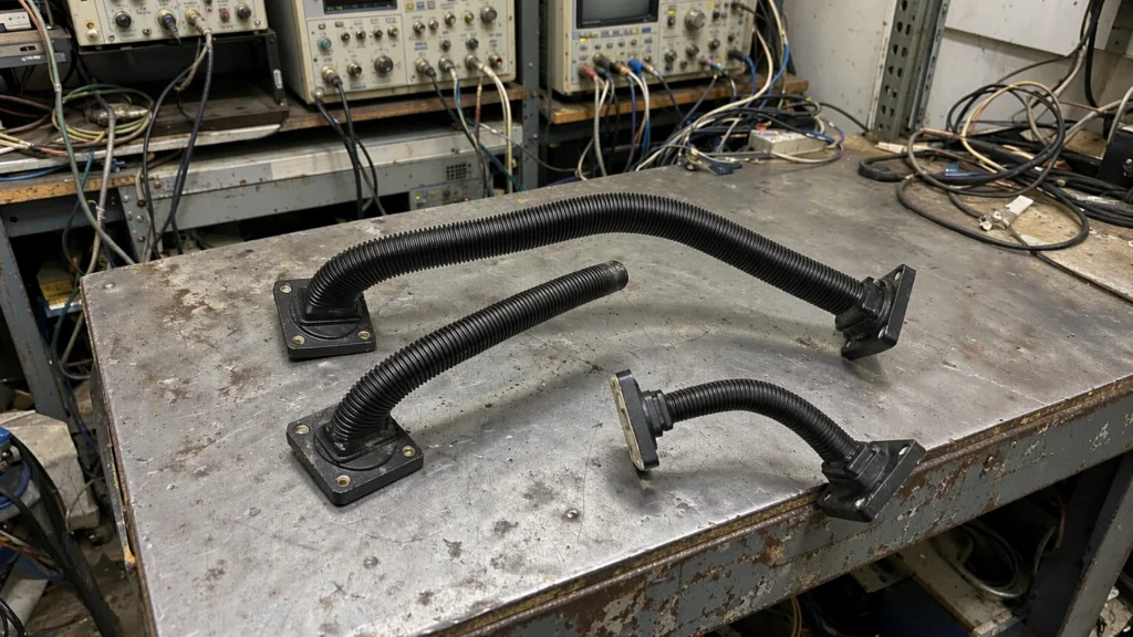
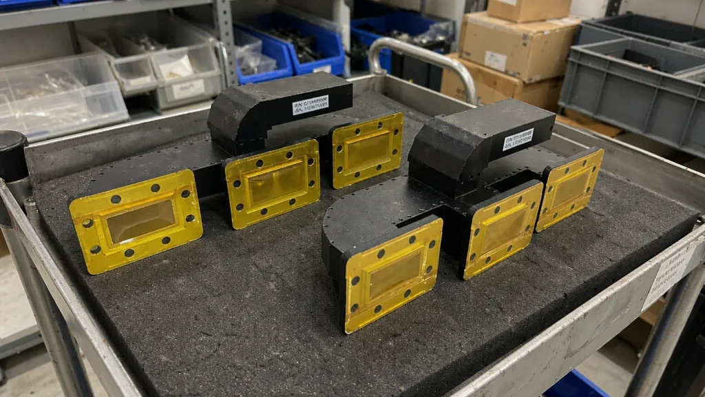
In the millimeter wave industry, waveguides are an important component that can transmit high-frequency signals from one point to another with minimal signal loss. A waveguide is a hollow metallic or dielectric structure that confines and guides electromagnetic waves within its boundaries. Its high power handling capabilities, low attenuation and low dispersion make it ideal

Millimeter Wave Products Processing by Dolph-Microwave Read More »

What are the frequency ranges for different frequency bands in circular waveguides

The frequency range of circular waveguides in different frequency bands varies according to their diameter. For example, in TE11 mode, a circular waveguide with a diameter of 22.86 mm operates at 7.3-10 GHz. Choose the appropriate diameter to match the required frequency range to ensure low-loss transmission. S-Band Characteristics At 3AM, ESA alerted us about

What are the frequency ranges for different frequency bands in circular waveguides Read More »

What are the corresponding circular waveguide diameters for each frequency band

What are the corresponding circular waveguide diameters for each frequency band?

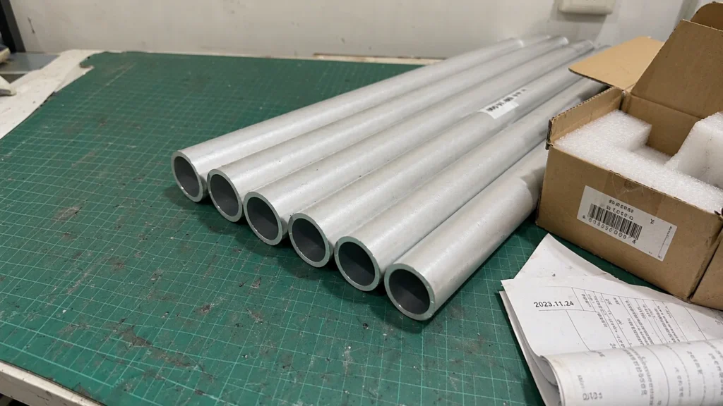
A circular waveguide refers to a waveguide with a circular cross-section. The lowest order propagation mode in a circular waveguide is TE11, which provides minimal signal degradation.The possible TM modes in circular waveguides are TM01, TM02, TM11, and TM12. The modes maintained by circular waveguides have many similarities with those of rectangular waveguides. For example,

What are the corresponding circular waveguide diameters for each frequency band? Read More »

What is a 4-port differential phase-shifted pulse high-power waveguide isolators?

What is a 4-port differential phase-shifted pulse high-power waveguide isolators?

The 4-port differential phase shift isolators is a combined waveguide device. When the microwave signal passes through the isolator, it can be transmitted with low loss in the forward direction and has high isolation in the reverse direction. It is composed of a 3dB combiner/divider, a parallel ferrite 90° non-reciprocal phase shifter, and a folded

What is a 4-port differential phase-shifted pulse high-power waveguide isolators? Read More »

How was complete coverage achieved with a minimum s-band antenna gain of -7 dBi

How was complete coverage achieved with a minimum s-band antenna gain of -7 dBi?

To achieve complete coverage with a minimum s-band antenna gain of -7 dBi, a straightforward configuration utilizing dual circularly polarized microstrip patch antennas was employed. The configuration involved the implementation of a wide bandwidth, dual circularly polarized truncated corner microstrip antenna, which was complemented by two parasitic patches. To enhance the cross polarization bandwidth, diagonally

How was complete coverage achieved with a minimum s-band antenna gain of -7 dBi? Read More »

What is the design emphasis for Dolph Microwave’ circulators

What is the design emphasis for Dolph Microwave’ circulators?

Dolph Microwave places significant design emphasis on optimizing the selection and bias point of the ferrite material used in their circulators. This prioritization is aimed at minimizing the insertion loss and maximizing the isolation at the desired frequency, bandwidth, and power level. By carefully choosing and biasing the ferrite material, Dolph Microwave ensures that the

What is the design emphasis for Dolph Microwave’ circulators? Read More »

What are the log-periodic antenna characteristics and performance results

What are the log-periodic antenna characteristics and performance results?

The log-periodic antenna is the main preferred form of the low-frequency UWB directional antenna. This antenna family has the remarkable capability to cover octave bandwidth or even UWB bandwidth of nearly 100 octaves. With a potential gain of up to 9 dB, it offers a significant boost to signal reception and transmission. At ultra-low frequencies,

What are the log-periodic antenna characteristics and performance results? Read More »

Scroll to Top
Blank Form (#3)