default

How to calibrate waveguide feed systems for optimal performance

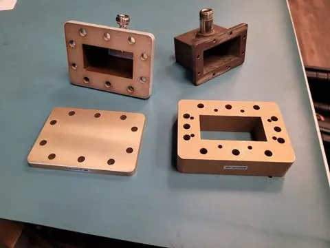
Calibrate waveguide feeds using a network analyzer: measure VSWR (target ≤1.2) and insertion loss (<0.5dB) across 8–12GHz, adjust phase/amplitude with SOLT standards for impedance matching. Check Connections and Cables These faults rarely cause complete failure but instead introduce intermittent signal loss, phase noise, and return loss degradation, often manifesting as a ​​3 dB to 6 […]

How to calibrate waveguide feed systems for optimal performance Read More »
How to measure waveguide antenna radiation patterns

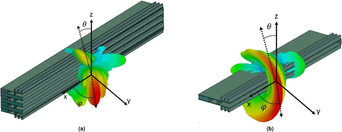
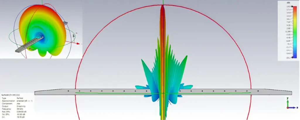
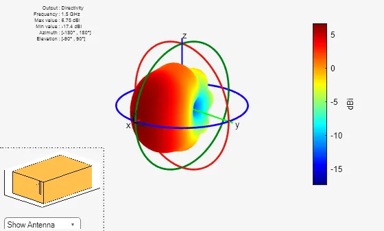
Measure a waveguide antenna’s radiation pattern by recording its received field or power versus angle at a stated frequency and polarization. Use a validated far-field range, or collect suitable near-field data and apply the corresponding transformation. A normalized pattern shows beam shape; absolute gain needs a separate amplitude reference and the appropriate corrections. Choose the

How to measure waveguide antenna radiation patterns Read More »

How to upgrade traditional antennas with waveguide technology

Upgrade traditional antennas by integrating a waveguide feed to replace the conventional dipole. This modification can boost gain by 3-6 dB and efficiently handle higher frequencies (2-40 GHz) with minimal loss. Precisely couple the waveguide port to the antenna’s feed point and ensure a weatherproof seal to prevent moisture degradation. Waveguide Basics Explained For a

How to upgrade traditional antennas with waveguide technology Read More »

What are the 5 steps to install a waveguide antenna system

To install a waveguide antenna system, first align its frequency (e.g., 12–18GHz for Ku-band) with the feed source to minimize insertion loss (<0.5dB). Secure the antenna to a stable mount using 5–8Nm torque, adjust elevation/azimuth via laser alignment, then calibrate VSWR (<1.5) with a network analyzer, and test signal strength (≥-80dBm) to confirm connectivity. Plan

What are the 5 steps to install a waveguide antenna system Read More »

How to select waveguide components for satellite communication

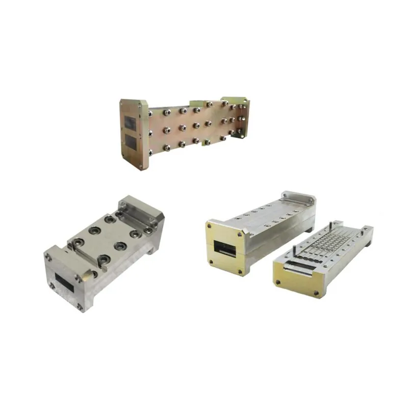
To select waveguide components for satellite communication, match their frequency (e.g., 12–18GHz for Ku-band) to the system’s operating range to minimize insertion loss (<0.5dB/cm). Use corrosion-resistant stainless steel or aluminum with joint gaps <0.1mm, and verify compliance with ITU-R S.465 standards for optimal signal integrity. Define Your Frequency Band​​ In satellite communications, this typically means

How to select waveguide components for satellite communication Read More »

What are the 5 latest trends in waveguide antenna technology

Recent waveguide antenna trends include: 26-40GHz millimeter-wave integration for 5G/satcom, boosting gain by 15% via 64-element phased arrays; carbon fiber composites reducing weight by 30% while maintaining <0.5dB insertion loss; RIS-enhanced designs improving beam efficiency by 5-8dB; and microchannel cooling enabling ±2℃ thermal stability at 100W/cm² power density. Integrated Antenna Design Over the past three

What are the 5 latest trends in waveguide antenna technology Read More »

How to troubleshoot waveguide antenna performance issues

To troubleshoot waveguide antenna performance, first measure VSWR with a tester (target <1.5; >1.5 indicates connector oxidation or misalignment). Use a 28GHz signal generator: if gain drops >2dB from spec, check waveguide flange joints for gaps. Rotate antenna to verify polarization—stable -30dBm±2dB signals confirm correct alignment. Ensure operation within 25±5℃, <60%RH to avoid thermal expansion

How to troubleshoot waveguide antenna performance issues Read More »

How to connect waveguide components to RF antennas

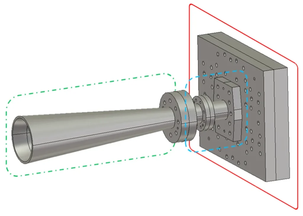
Connect waveguide components to RF antennas using precisely aligned flanges (e.g., CPR-229) to minimize signal loss. Seal joints with conductive gaskets or copper tape to maintain an airtight, low-VSWR interface (<1.2:1 ideal). Use a torque wrench to tighten flange bolts to the specified value (e.g., 25 in-lbs) for consistent electrical continuity. ​​Waveguide and Antenna Interface

How to connect waveguide components to RF antennas Read More »

What is the role of waveguide duplexers in communication systems

Waveguide duplexers are crucial for allowing a single antenna to simultaneously transmit and receive signals, often operating in frequency ranges like 3.5-4.2 GHz. They use internal filters to provide high isolation, typically over 30 dB, preventing powerful transmitted signals from overwhelming sensitive receivers, which is vital in radar and cellular systems. What is a Waveguide

What is the role of waveguide duplexers in communication systems Read More »

What are the 4 advantages of waveguide amplifiers over RF amplifiers

Waveguide amplifiers surpass RF amplifiers with higher frequency support (30-300GHz vs. <6GHz), lower insertion loss (<0.5dB vs. 1.2dB typical), 2-3× greater power capacity (100W+ vs. 20-30W), and broader bandwidth (>10GHz vs. ≤2GHz), optimizing high-frequency transmission efficiency. ​​Handles High Power Signals​​ While a typical coaxial-based RF amplifier might comfortably handle powers up to 500 watts, it

What are the 4 advantages of waveguide amplifiers over RF amplifiers Read More »

Scroll to Top
Blank Form (#3)