Waveguide flange specifications determine whether two components align, make the intended electrical contact and meet the joint’s sealing requirements. Matching the waveguide size alone is insufficient: the flange face, bolt pattern, alignment pins and gasket arrangement must also match. A joint that bolts together can still introduce mismatch or poor measurement repeatability.
Match the complete interface, not just the WR size
A waveguide designation identifies the transmission-line size; it does not fully define the mating flange. Specify the flange designation and applicable drawing revision on both sides of the joint. For a custom interface, an approved drawing takes the place of an assumed standard match.
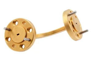
Compare the waveguide flange options against these mating features before ordering:
- Aperture: width, height, corner geometry and position relative to the flange datums.
- Fasteners: hole positions, clearance or threaded holes, thread specification and available bolt engagement.
- Alignment: pin and dowel-hole locations, fits and the viewing direction used in the drawing.
- Face configuration: contact surfaces, grooves, choke features and any required mating combination.
- Seal: gasket profile, groove dimensions, material compatibility and compressed condition.
Two circular flanges with similar outside diameters are not necessarily interchangeable. Use the flange size and gasket-fit guide to organize the comparison, then verify the actual mating drawings.
Separate alignment, electrical contact and sealing
Lateral or angular displacement changes the transition between waveguide apertures. Surface damage, debris or an incorrectly assembled face can also change the joint. NIST’s research on imperfect test ports shows why the interfaces between calibration standards, test ports and the device under test must be considered in precision waveguide measurements.[1]
A pressure-tight seal does not by itself prove acceptable RF performance. Likewise, a low-reflection VNA measurement does not establish a leak rate. If both are required, define separate RF and sealing acceptance tests.
Do not add a gasket to a joint simply because another flange uses one. The seal must fit the intended groove and compression condition without obstructing the aperture or preventing the designed faces from seating.
Specify RF acceptance at a defined reference plane
State the operating band, maximum permitted reflection and any insertion-loss limit for the assembled component or joint. Also state the calibration method and reference planes; otherwise, adapters and other parts of the test setup may be included in the result.
VSWR and return loss describe reflection. They do not measure flange leakage, dissipative loss or power-handling capability on their own. For a measured VSWR:
|Γ| = (VSWR − 1) / (VSWR + 1)
Reflected power fraction = |Γ|2
Return loss = −20 log10|Γ| dB
- VSWR 1.20 corresponds to approximately 0.83% reflected power and 20.83 dB return loss.
- VSWR 1.50 corresponds to 4.00% reflected power and 13.98 dB return loss.
These are calculated relationships at the measurement reference plane, not Dolph product ratings or a way to assign all measured reflection to one flange. Use the RF test and measurement component guide when defining calibration hardware and adapter placement.
Use the joint’s assembly procedure for torque
There is no single bolt torque suitable for every waveguide flange. Fastener size and material, thread condition, flange construction and gasket compression all affect the assembly requirement. Use the approved component or joint procedure, including its tightening sequence and lubrication condition.
Align and support the components before tightening. Do not use bolts to pull a visibly misaligned assembly into position. Inspect the mating surfaces and pins, remove contamination using a compatible cleaning procedure, and reject damage that prevents correct seating.
Check repeatability when the connection will be remade
One successful connection is not enough to characterize a repeatedly assembled test interface. Record a baseline, disconnect and reconnect under the same procedure, then compare the measured S-parameters across the required band. Keep cable position and other test conditions controlled so that the result reflects the connection being assessed.
PTB includes interface repeatability alongside calibration-standard uncertainty, cable movement and VNA characteristics in its waveguide measurement uncertainty analysis. That supports treating reconnect variation as a measured contribution rather than assuming every assembly is identical.[2]
Include these requirements in a flange RFQ
Send the waveguide size and operating band, both mating drawings, flange designations, material and finish requirements, seal or pressurization conditions, and required inspection records. For an assembly, include its support arrangement and any access limits for bolts or alignment pins.
If RF acceptance is required, specify the reflection and transmission limits, reference planes and whether reconnect repeatability must be assessed. Attach these details through Dolph’s inquiry form so the interface can be reviewed against the actual mating component.