
Waveguide Components for RF Test & Measurement
Connect instruments, establish calibration reference planes and sample RF power with waveguide hardware matched to your test setup.

Start with the measurement.
Dolph Microwave supplies calibration kits, adapters, couplers, horns and custom assemblies for RF test systems. A component can be an instrument interface, a calibration standard or part of the device under test. Its role determines which losses, reflections and connections must be included in the measurement.
VNA calibration & verification
Choose the kit for the complete frequency sweep, waveguide cross-section, mating flange and calibration method supported by your vector network analyzer. Standard rectangular and double-ridged waveguide require different standards and interface definitions.
Define where the calibrated reference planes sit. An adapter outside those planes contributes to the measured result unless it is separately characterized and removed with an appropriate correction. Ask for the kit definitions and a verification procedure, not just a list of physical parts.
Instrument interfaces & test fixtures
Use a waveguide-to-coax adapter where the instrument and test article have different transmission-line interfaces. Specify the coaxial connector family and sex, waveguide designation, flange drawing and orientation.
Include adapter loss and mismatch in the test plan. Adding an adapter after calibration changes the signal path. Support rigid assemblies so their weight does not load the instrument connector, and confirm that bends and flange fasteners remain accessible inside the fixture.

Forward & reflected power
A directional coupler samples a small portion of the main-line signal. Select coupling and directivity across the required band, then check the sampled level against the sensor’s measurement range and damage limit.
Specify average power, peak power, pulse width and duty cycle separately. Directivity limits how well the setup separates forward and reflected waves. Terminate unused ports with suitable matched loads and include the sample-path attenuation in the power calculation.

Antenna & chamber measurements
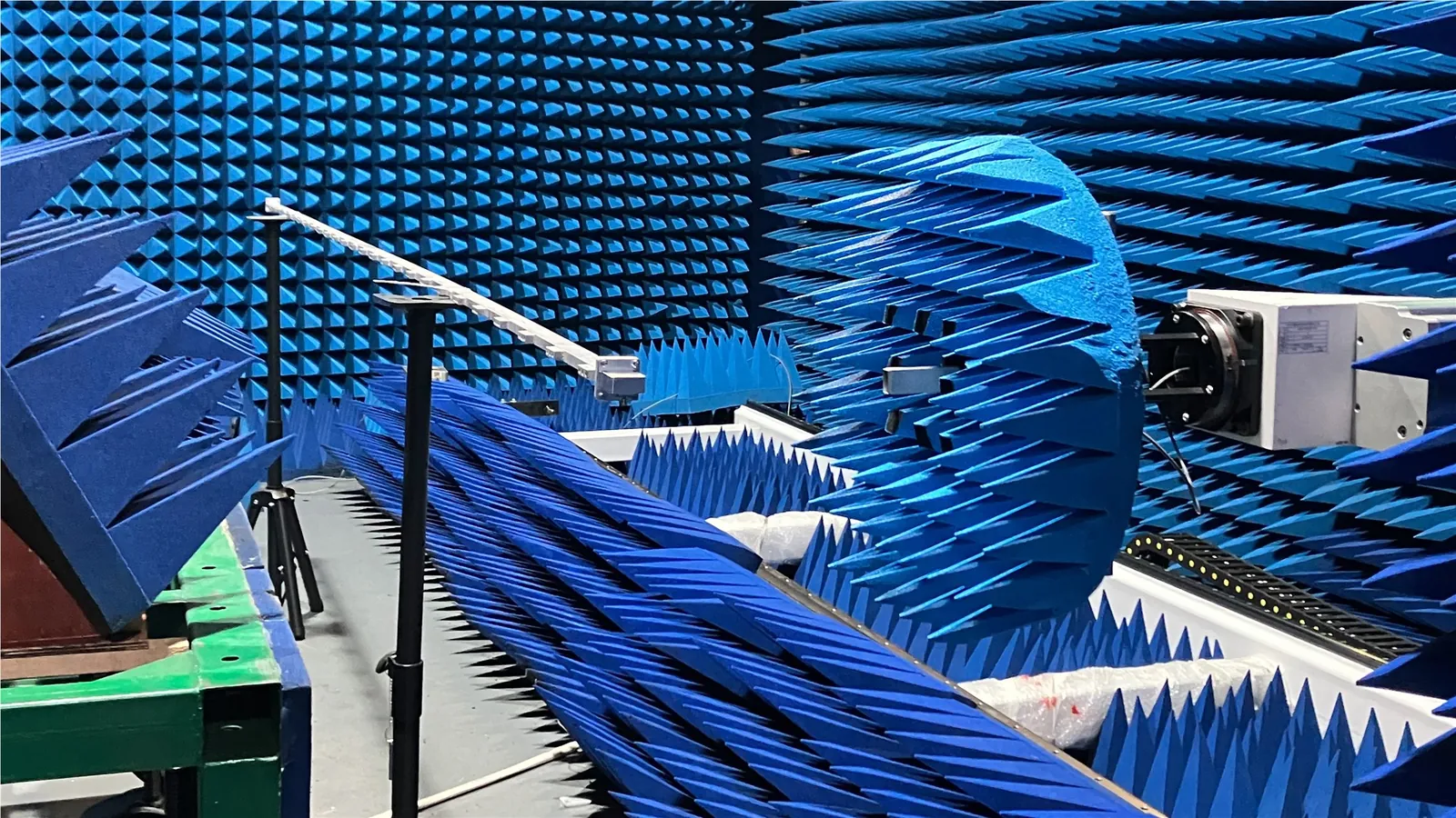
Select a horn or feed for the test band, polarization, mounting arrangement and required measurement geometry. Check clearance for rotation, cable routing and alignment before fixing the interface drawing.
If the horn will serve as a gain reference, specify the required calibration data and uncertainty. A nominal gain value is not a substitute for a calibrated gain-versus-frequency record. Agree the test distance and near-field or far-field method with the antenna test plan.

Match the component to the test.
Use this checklist to define the required configuration. Frequency coverage, power handling and measurement limits are model-specific; confirm them in the quotation and drawing.
| Test requirement | Component family | What to specify |
|---|---|---|
| Two-port S-parameters | Calibration and verification kits | VNA model, sweep limits, waveguide size, flange, calibration method, kit definitions and verification standards. |
| Coax-to-waveguide connection | Waveguide-to-coax adapters | Connector family and sex, flange drawing, operating band, insertion loss, return loss and mechanical support. |
| Power sampling | Directional couplers and matched loads | Coupling, directivity, sample-port connector, sensor limits, average and peak power, and cooling conditions. |
| Antenna characterization | Standard gain horns and feed horns | Frequency, polarization, gain data, mounting, alignment, chamber geometry and calibration documentation. |
| Multi-path production testing | Waveguide switches | Port arrangement, switch states, control interface, switching time, isolation, life requirement and measurement repeatability. |
| Routing inside a fixture | Custom waveguide assemblies | Interface drawings, available envelope, bend orientation, support points, flange access and agreed RF acceptance limits. |
For switches, state whether RF will be present during switching. Do not assume a component is rated for hot switching.
Check the complete signal path.
Matching the center frequency alone does not establish compatibility. Review the electrical band, mechanical interfaces and calibration boundary together.
Band & propagation
Provide minimum and maximum frequency. Use each component’s specified operating band, not the waveguide cutoff alone. Confirm that adapters, loads, standards and the test article all cover the intended sweep.
Flanges & alignment
Match aperture, flange designation, bolt pattern, alignment features and any gasket or choke arrangement. Use the flange reference with the actual mating drawing. Follow the specified assembly torque rather than a universal torque value.
Loss & repeatability
Set limits for the assembled path. Record connection order and support conditions; check a verification device after reconnection or a fixture change. Ask for repeatability data when the test repeatedly changes paths or reconnects parts.
A simple sample-power check
With an assumed 30 dB coupling factor, 1 W of main-line power gives an ideal 1 mW sample before sample-path loss: Psample = Pmain × 10−C/10. This is an arithmetic example, not a Dolph product rating. Apply the actual coupling calibration, frequency response, mismatch and power-sensor limits.
Define what a passing part looks like.
Give Dolph the test conditions and acceptance limits before manufacture. Available machining and test resources are described on the manufacturing capability page; confirm the required band, fixture and report scope for your order.
- Part identification: drawing revision, model, serial number where required, and port identification.
- Measured results: agreed S-parameters, coupling, isolation or other applicable quantities across the specified sweep.
- Measurement conditions: calibration method, reference planes, power level, fixture, temperature and any de-embedding.
- Acceptance record: limits, measured values and pass/fail decision; request uncertainty and the decision rule where needed.
Measurement traceability belongs to a documented measurement result and calibration chain. It is not established by an instrument brand or a product photograph.[1]
For a calibration kit or measurement system, specify the uncertainty and traceability documentation you need in the RFQ. NIST’s microwave calibration work treats calibration characterization and uncertainty propagation as part of the measurement process.[2]
Questions before you specify.
Can I select a waveguide component by frequency alone?
No. The operating band must match, but so must the waveguide cross-section, flange, connector and power conditions. Two parts with overlapping frequency ranges may not mate mechanically or support the same test configuration.
Can I use one calibration kit for standard and double-ridged waveguide?
Do not assume interchangeability. The apertures, flange interfaces and calibration-standard definitions differ. Select the kit for the waveguide family and the calibration procedure used by your analyzer.
Should I calibrate before or after the adapter?
Choose the reference plane required by the measurement. Calibration at the waveguide interface can account for the preceding instrument path when the method and standards support it. If the adapter remains beyond the calibrated plane, its response remains in the measurement unless a validated correction removes it.
Does a low VSWR guarantee low measurement uncertainty?
No. VSWR describes impedance match. Total measurement uncertainty can also include calibration-standard uncertainty, drift, noise, connector repeatability, directivity and fixture effects. Set the uncertainty requirement for the complete measurement.
What data should I request with a horn antenna?
State whether you need a nominal specification or a calibrated reference. For a reference antenna, define gain-versus-frequency data, polarization, reference interface, calibration conditions and uncertainty. Confirm these deliverables before ordering.
Can Dolph build a custom waveguide test assembly?
Send the mating drawings, frequency range, available space, port orientation and RF acceptance limits. Dolph can review a custom assembly against its manufacturing capabilities. Include a fixture sketch and access requirements for fasteners, supports and switching controls.
Send the setup. Specify the right parts.
Share a drawing, test schematic or instrument-to-DUT connection list. Identify which parts you need and which interfaces are already fixed, so Dolph can review a standard configuration or a custom assembly.
Have an existing part number? Include it with the drawing revision and required quantity.
- Frequency & measurementMinimum and maximum frequency, test task and required RF limits.
- Interfaces & equipmentWR or WRD designation, flange drawing, coaxial connector and instrument model.
- Power & environmentAverage/peak power, pulse conditions, temperature, cooling and pressure if applicable.
- Mechanical scopePort orientation, installation space, mounting points and drawing or CAD file.
- Delivery & documentationQuantity, required date, dimensional report, RF data and calibration records.