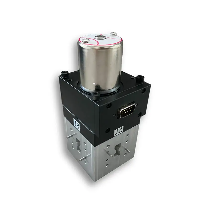
Waveguide Switches
Dolph Microwave double-ridged waveguide switches are available in SPDT and DPDT configurations for WRD840 through WRD180 waveguide sizes. Listed model bands cover 0.84-2.0 GHz through 18.0-40.0 GHz, with 1.15:1 VSWR, 65 dB isolation, latching actuation, cover or grooved flange options, and 22~32 VDC actuator power.
Double-Ridged Waveguide Switches
Dolph Microwave double-ridged waveguide switches are available in SPDT and DPDT configurations across the listed WRD waveguide sizes. The model table covers individual frequency bands from 0.84-2.0 GHz through 18.0-40.0 GHz.
Each listed model specifies a latching actuator, 1.15:1 VSWR, 65 dB isolation and 22~32 VDC actuator power. Insertion loss and switching time vary by waveguide size. Cover and grooved flange designations are provided for system matching.
Combined coverage of listed model bands
Two switch configurations listed
Specified across the listed table
Specified for all listed models
Waveguide Switch Specifications
Select the required model by matching the operating frequency range, WRD waveguide size, SPDT or DPDT configuration, switching time and mating flange designation.
| Model | Frequency Range (GHz) |
WG Size | VSWR | IL (dB) | Isolation (dB) | Switch Time (mSec) |
Actuator | Switch Type | Voltage (VDC) | Cover Flange | Grooved Flange | Datasheet | 3D Model |
|---|---|---|---|---|---|---|---|---|---|---|---|---|---|
| DH-840DRWDESMD… | 0.84-2.0 | WRD840 | 1.15:1 | 0.2 | 65 | 120 | Latching | DPDT | 22~32 | FPWRD840U24 | FMWRD840U24 | STEP | |
| DH-840DRWESMD… | 0.84-2.0 | WRD840 | 1.15:1 | 0.2 | 65 | 120 | Latching | SPDT | 22~32 | FPWRD840U24 | FMWRD840U24 | STEP | |
| DH-150DRWDESMD… | 1.5-3.6 | WRD150 | 1.15:1 | 0.2 | 65 | 120 | Latching | DPDT | 22~32 | FPWRD150D24 | FMWRD150D24 | STEP | |
| DH-150DRWESMD… | 1.5-3.6 | WRD150 | 1.15:1 | 0.2 | 65 | 120 | Latching | SPDT | 22~32 | FPWRD150D24 | FMWRD150D24 | STEP | |
| DH-200DRWDESMD… | 2.0-4.8 | WRD200 | 1.15:1 | 0.2 | 65 | 120 | Latching | DPDT | 22~32 | FPWRD200D24 | FMWRD200D24 | STEP | |
| DH-200DRWESMD… | 2.0-4.8 | WRD200 | 1.15:1 | 0.2 | 65 | 120 | Latching | SPDT | 22~32 | FPWRD200D24 | FMWRD200D24 | STEP | |
| DH-250DRWDESMD… | 2.6-7.8 | WRD250 | 1.15:1 | 0.3 | 65 | 120 | Latching | DPDT | 22~32 | FPWRD250D30 | FMWRD250D30 | STEP | |
| DH-250DRWESMD… | 2.6-7.8 | WRD250 | 1.15:1 | 0.3 | 65 | 120 | Latching | SPDT | 22~32 | FPWRD250D30 | FMWRD250D30 | STEP | |
| DH-350DRWDESMD… | 3.5-8.2 | WRD350 | 1.15:1 | 0.4 | 65 | 120 | Latching | DPDT | 22~32 | FPWRD350D24 | FMWRD350D24 | STEP | |
| DH-350DRWESMD… | 3.5-8.2 | WRD350 | 1.15:1 | 0.4 | 65 | 120 | Latching | SPDT | 22~32 | FPWRD350D24 | FMWRD350D24 | STEP | |
| DH-475DRWDESMD… | 4.75-11.0 | WRD475 | 1.15:1 | 0.4 | 65 | 120 | Latching | DPDT | 22~32 | FPWRD475D24 | FMWRD475D24 | STEP | |
| DH-475DRWESMD… | 4.75-11.0 | WRD475 | 1.15:1 | 0.4 | 65 | 120 | Latching | SPDT | 22~32 | FPWRD475D24 | FMWRD475D24 | STEP | |
| DH-500DRWDESMD… | 5.0-18.0 | WRD500 | 1.15:1 | 0.4 | 65 | 120 | Latching | DPDT | 22~32 | FPWRD500D36 | FMWRD500D36 | STEP | |
| DH-500DRWESMD… | 5.0-18.0 | WRD500 | 1.15:1 | 0.4 | 65 | 120 | Latching | SPDT | 22~32 | FPWRD500D36 | FMWRD500D36 | STEP | |
| DH-580DRWDESMD… | 5.8-16.0 | WRD580 | 1.15:1 | 0.35 | 65 | 80 | Latching | DPDT | 22~32 | FPWRD580D28 | FMWRD580D28 | STEP | |
| DH-580DRWESMD… | 5.8-16.0 | WRD580 | 1.15:1 | 0.35 | 65 | 80 | Latching | SPDT | 22~32 | FPWRD580D28 | FMWRD580D28 | STEP | |
| DH-650DRWDESMD… | 6.5-18.0 | WRD650 | 1.15:1 | 0.35 | 65 | 80 | Latching | DPDT | 22~32 | FPWRD650D28 | FMWRD650D28 | STEP | |
| DH-650DRWESMD… | 6.5-18.0 | WRD650 | 1.15:1 | 0.35 | 65 | 80 | Latching | SPDT | 22~32 | FPWRD650D28 | FMWRD650D28 | STEP | |
| DH-700DRWDESMD… | 7.0-18.5 | WRD700 | 1.15:1 | 0.35 | 65 | 80 | Latching | DPDT | 22~32 | FPWRD700D26 | FMWRD700D26 | STEP | |
| DH-700DRWESMD… | 7.0-18.5 | WRD700 | 1.15:1 | 0.35 | 65 | 80 | Latching | SPDT | 22~32 | FPWRD700D26 | FMWRD700D26 | STEP | |
| DH-750DRWDESMD… | 7.5-18.0 | WRD750 | 1.15:1 | 0.4 | 65 | 80 | Latching | DPDT | 22~32 | FPWRD750D24 | FMWRD750D24 | STEP | |
| DH-750DRWESMD… | 7.5-18.0 | WRD750 | 1.15:1 | 0.4 | 65 | 80 | Latching | SPDT | 22~32 | FPWRD750D24 | FMWRD750D24 | STEP | |
| DH-110DRWDESMD… | 11.0-26.5 | WRD110 | 1.15:1 | 0.4 | 65 | 80 | Latching | DPDT | 22~32 | FPWRD110C24 | FMWRD110C24 | STEP | |
| DH-110DRWESMD… | 11.0-26.5 | WRD110 | 1.15:1 | 0.4 | 65 | 80 | Latching | SPDT | 22~32 | FPWRD110C24 | FMWRD110C24 | STEP | |
| DH-180DRWDESMD… | 18.0-40.0 | WRD180 | 1.15:1 | 0.4 | 65 | 80 | Latching | DPDT | 22~32 | FPWRD180C24 | FMWRD180C24 | STEP | |
| DH-180DRWESMD… | 18.0-40.0 | WRD180 | 1.15:1 | 0.4 | 65 | 80 | Latching | SPDT | 22~32 | FPWRD180C24 | FMWRD180C24 | STEP |
How to Select a Waveguide Switch
1. Match the Frequency Range
Start with the complete required operating band. Each WRD switch series has a specified frequency range, and several listed ranges overlap.
2. Confirm the Waveguide Size
The selected switch must match the WRD size of the adjoining waveguide assembly. Frequency range alone is not sufficient for final selection.
3. Select SPDT or DPDT
Both SPDT and DPDT versions are listed for every included waveguide size. Use the configuration specified by the RF routing design.
4. Check Switching Time
The listed switching time is 120 mSec for WRD840 through WRD500 and 80 mSec for WRD580 through WRD180.
5. Confirm the Flange
Cover and grooved flange designations are listed for each WRD size. Confirm the mating interface before placing an order.
6. Confirm Material and Finish
The part-number guide identifies Aluminium and Cu material options. Other finishes and paint colors are available upon request.
Part Number Guide
The supplied ordering example is:
- 840DR – Waveguide size: WRD840
- WDESM – Switch type: DPDT
- WESM – Switch type: SPDT
- D – Drive type: Combined Manual and Motorized
- P – Flange type: Rectangular Flat
- M – Flange type: Rectangular Grooved
- A/C – Material: Aluminium or Cu
- TTL – Actuator control: TTL Electrical
Waveguide Switch FAQ
What frequency ranges are available?
The listed individual bands begin at 0.84-2.0 GHz for WRD840 and extend to 18.0-40.0 GHz for WRD180.
Are SPDT and DPDT configurations available?
Yes. Both SPDT and DPDT models are listed for every waveguide size included in the technical table.
What VSWR and isolation values are listed?
All models in the supplied table specify 1.15:1 VSWR and 65 dB isolation.
What switching times are available?
The table lists switching times of either 80 mSec or 120 mSec, depending on the selected waveguide size.
What actuator voltage is listed?
The listed actuator power-voltage range is 22~32 VDC.
Which flange configurations are available?
Cover and grooved flange designations are provided for every listed waveguide size.
Can the surface finish or paint color be changed?
The table note states that other finishes and paint colors are available upon request.
Waveguide Switch Downloads
Use the product-series document for switch selection and the flange reference document to check the required double-ridged flange designation.
Request a Waveguide Switch Quote
Include the following information so the required configuration can be checked against the listed model range:
- Operating frequency range
- Required WRD waveguide size
- SPDT or DPDT configuration
- Required switching time
- Cover or grooved flange
- Required flange designation
- Aluminium or Cu material
- TTL electrical control requirement
- Required finish or paint color
- Required quantity