
Catalog Model
Give us the product family, operating band, WR size, flange and quantity. If you already picked a model, send the PDF or STEP link.
Standard and custom waveguide — we make them in Xi’an
Source individual components, matched interfaces or custom assemblies from one factory. We review your frequency band, WR size, flange, connector, power, pressure, routing, finish and test requirements before we quote.
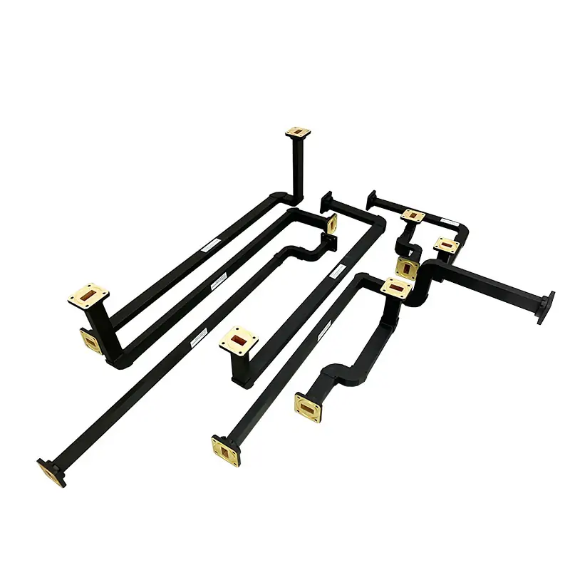
Product families by function
Use the linked family pages for catalog models. If you need several functions built as one assembly, send us the complete RF path and we’ll review it together.
Fixed lengths, E-plane bends, H-plane bends, miter bends and routed sections.
Waveguide-to-coax, size changes, rectangular-to-circular and special interfaces.
Alignment sections, vibration accommodation and preformed flexible routing.
Forward or reflected sampling, probe coupling and near-field measurement hardware.
Pressure windows, inlets, bulkhead feedthroughs, seals and mating hardware.
Low-power and high-power terminations, fixed attenuation and water-cooled loads.
Rotary joints plus manual or motorized switching for moving RF paths.
TRL kits, shorts, shims, gaskets, flange references, supports and dust covers.
Four ways to order
How we quote depends on how much of your RF path is already fixed. Send what you have — we can fill in the missing info before pricing.
Give us the product family, operating band, WR size, flange and quantity. If you already picked a model, send the PDF or STEP link.
Keep the electrics and change the flange, connector orientation, length, finish, mounting points or installation envelope.
Send us the old part number, drawing, measured dimensions and mating interfaces. Tell us if anything needs to change from the original.
Combine bends, straights, transitions, flex sections, couplers or flanges into one tested RF path from a system drawing or sketch.
Standard product ranges
The numbers below describe family ranges, not a single universal spec. Final frequency, flange, power and environment specs are confirmed per model — not assumed across the whole family.
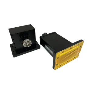
Right-angle and end-launch configurations with N, SMA, 2.92 mm, 2.4 mm and 1.85 mm connector options by model.
Published family range: 0.32 to 67 GHz Published sizes: WR2300 to WR19
E-plane, H-plane and custom-angle routing with length, radius, flange and finish changes available for selected models.
Published standard range: 1.72 to 110 GHz Published sizes: WR430 to WR10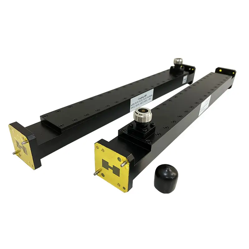
Waveguide or coaxial sample ports, single- or dual-direction monitoring and several port arrangements.
Published range: 1.13 to 40 GHz, WR650 to WR28 Published coupling: 3 to 40 dB by configuration Combined straights, bends, flexible sections and end interfaces built from detailed drawings or simple marked-up sketches.
Published scope: L band through W band Drawing, sketch and replacement-part routesInformation that controls the quote
A part number alone might not tell us the flange, connector orientation, power class, sealing requirement or space limits. Add the limits that can’t change.
How we make them
We do CNC milling and turning, waveguide forming and bending, brazing, assembly and dimensional inspection in-house. The actual process depends on the material and shape of your part.

Flanges, bodies, transitions, coupling features and mounting details machined to your drawing tolerances.

Rigid, preformed and routed sections produced for the required bend plane, angle, radius and installation space.

Joined assemblies can combine multiple sections and interfaces before dimensional and RF verification.
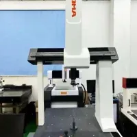
We use coordinate measurement for dimensional checks. Tell us in the RFQ if you need inspection reports with delivery.
Measurement and testing services
We offer RF, antenna, high-power, calibration and environmental testing. Before we release the order, confirm the exact method, frequency range, fixture, acceptance limit and report format you want.
We can measure up to 100 GHz. Tell us the S-parameters you need, frequency points, calibration method and acceptance limits.
Use when a supplied horn, probe, feed or assembly needs antenna-related verification rather than component-only RF data.
State average power, peak power, duty cycle, pulse width, cooling, pressurization and the required proof condition.
Calibration hardware and TRL kit requirements can be added when the component will be used with a VNA test setup.
Define the applicable test request and acceptance criteria instead of assuming that every order includes EMC-related evidence.
The published list includes temperature, altitude, salt fog and humidity. State the test profile and required record before quotation.
Order support for different situations
What we need depends on what you’re ordering. Sending the right starting info cuts down on back-and-forth questions.
Send function, band, WR size, interfaces, power, environment and quantity for a catalog-model shortlist.
Send the old part number, dimensional drawing, photos and mating hardware. Mark any allowed design changes.
Attach PDF or STEP data and identify critical dimensions, datums, tolerances, finish and required inspection records.
Send the system route and interface list so several components can be reviewed as one assembly.
About the supplier
Use the company, product, manufacturing and support pages to verify what we do. Product specs and compliance are model-dependent — not blanket across everything.
Send us your RFQ — no form needed
Attach whatever engineering data you have. We can review a catalog model, replacement part, modified interface or complete waveguide assembly — email is fine.