
Standard Rectangular Waveguide Components
Select rectangular waveguide components by operating band, WR size and the complete mating interface. Dolph Microwave supplies straight sections, bends, flexible sections, adapters, switches and calibration hardware. Use the selected model’s data for RF limits; one family-wide frequency or power figure cannot define every configuration.
Choose the product family

Straight waveguide sections
Specify WR size, flange pair, overall length, material and finish for a rigid connection.
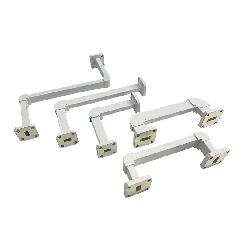
Miter bends
Match the bend plane, angle, port orientation and available mechanical envelope.
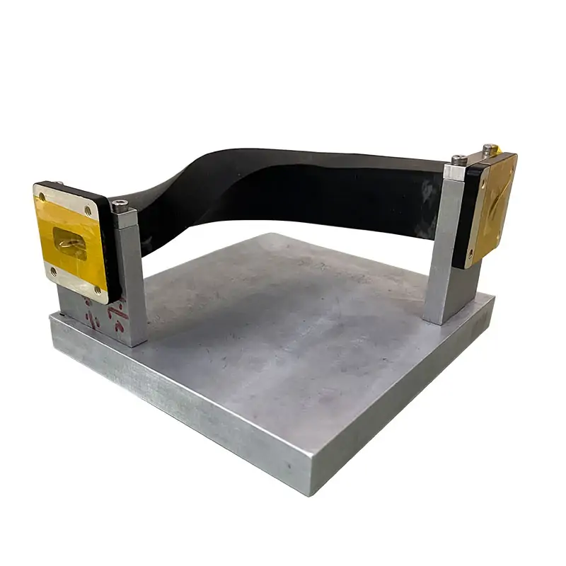
Flexible waveguide
Check bend and twist limits, installed routing and whether movement is static or repeated.
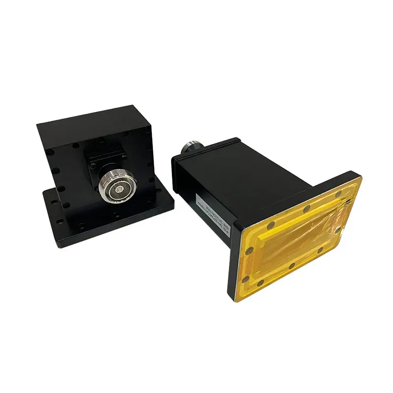
Waveguide-to-coax adapters
Identify the waveguide flange, coaxial connector type and gender, and required operating band.
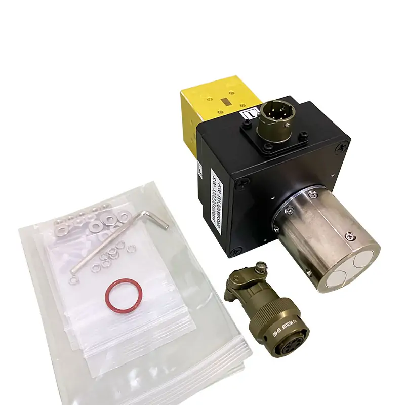
Manual and motorized switches
Specify the port arrangement, switching states, control interface and power conditions.

Rectangular calibration kits
Match the calibration method, reference planes, flange type and required kit definitions.
Build the specification around both interfaces
| Selection input | What to specify |
|---|---|
| Operating band | Give the lowest and highest test or operating frequency. Check the complete band against the selected model. |
| Waveguide and flange | State the WR size and the full flange designation at each end. Include a drawing when the interface is uncertain. |
| RF limits | Define maximum VSWR or return loss and insertion loss, with the measurement band and acceptance conditions. |
| Power and environment | Separate CW and peak power; include pulse width and duty cycle where relevant. Specify pressure, cooling and temperature requirements. |
| Mechanical fit | Provide overall length, bend plane, twist orientation, mounting points and available space. |
| Documentation | Request the applicable drawing revision, model-specific datasheet and agreed inspection or RF test record. |
Check the joint before adding another component
A matching WR designation does not establish flange, gasket or bolt-pattern compatibility. Use the flange measurement guide to record the interface when a drawing is unavailable.
For a laboratory setup, define the calibration reference planes before selecting adapters and test sections. The RF test and measurement guide connects component choice with the measurement arrangement.
Several bends and transitions may be better specified as one custom waveguide assembly. Supply the complete route, including service access and mating equipment.
Questions before you specify the hardware
Can I choose a component from frequency alone?
No. Frequency selects candidate models; flange geometry, power, routing and RF limits determine whether a candidate fits the system.
Does one listed rating apply to every size?
No. Use the row and document revision for the selected model. Treat typical performance separately from an acceptance limit.
Send the band and both mating interfaces
Include the WR size, flange drawings, RF limits, power, mechanical envelope and quantity. Mark unknown requirements so they can be resolved before quotation.