
Waveguide Components for Microwave Systems
Build the RF path around compatible transmission sections, interfaces, signal-control devices and test hardware. Dolph Microwave’s waveguide range includes standard rectangular and double-ridged components, antenna-feed interfaces and drawing-based assemblies. Start with the required function, then select the model and interfaces.
Choose the product family
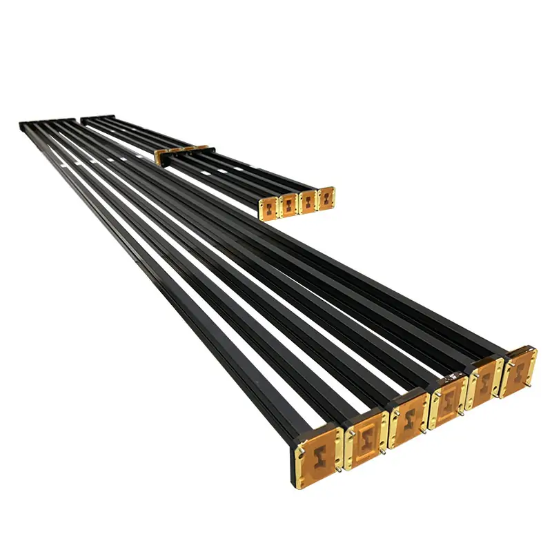
Double-ridged transmission sections
Match the WRD family and both flange faces to the adjoining equipment.
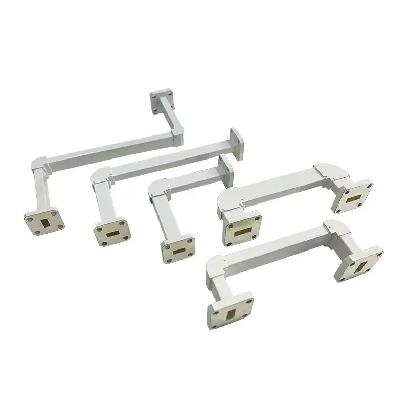
Routing and bends
Choose the plane, angle, length and flange orientation needed by the installation.
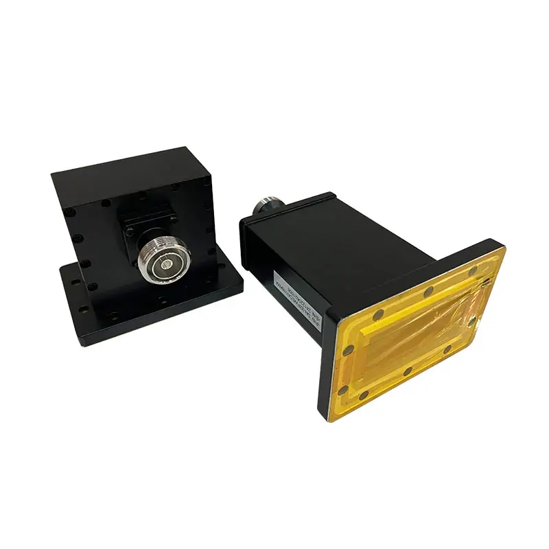
RF interfaces
Connect waveguide and coaxial hardware with the correct band, connector and power rating.

Isolators and circulators
Compare isolation, insertion loss, port direction and forward or reflected power conditions.
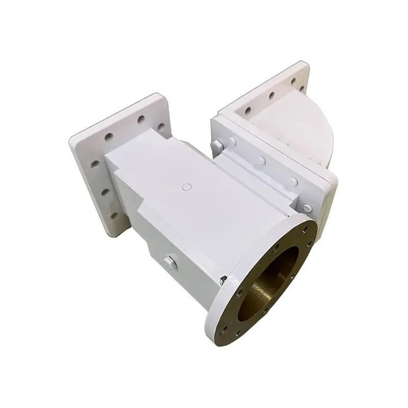
OMTs and feed interfaces
Specify the polarization ports, operating bands and mechanical interfaces of the feed network.

Calibration and verification
Select standards for the actual test port, calibration method and measurement band.
Choose the waveguide family before the individual part
Standard rectangular waveguide
Use this route when the equipment specifies rectangular WR interfaces. Compare component rows and complete flange drawings.
Double-ridged waveguide
Use the WRD family required by the system. Overlapping model bands do not make different WRD interfaces interchangeable.
Custom assemblies
Supply a drawing or path sketch when several functions must fit within one mechanical envelope.
Specify performance at the system boundary
| Selection input | What to specify |
|---|---|
| Interfaces | Record both waveguide sections, flange faces, coaxial connectors and port orientation. |
| Transmission | State the operating band, permitted reflection and insertion loss for the relevant path. |
| Signal control | For couplers, specify coupling and directivity; for switches, port states; for ferrite devices, isolation and direction. |
| Power | Identify CW and peak power, duty cycle, reflected-power condition and cooling requirements. |
| Assembly | Include pressure boundaries, supports, service access, available length and environmental conditions. |
| Acceptance | Agree the model drawing, test conditions and required records before releasing the order. |
Keep pressure sealing and RF matching separate
A sealed assembly needs compatible windows, gas connections, gaskets and mating flanges. Review pressure and sealing components as a system rather than assigning one part’s pressure rating to the entire run.
For test hardware, use waveguide components for RF test and measurement to define the reference planes and connection sequence. RF acceptance data should correspond to the assembled configuration that will be supplied.
Questions before you specify the hardware
Can standard and double-ridged parts be connected directly?
Use a specified transition when the interfaces differ. Confirm both port geometries and the common operating band.
What should I send without a part number?
Send the operating band, photos or drawings of both interfaces, RF function, power and available space. A complete model number can follow the configuration review.
Start with an RF path sketch
Mark component functions, port interfaces, frequency, power and mechanical constraints. Include quantity and the test documents required with delivery.