Waveguide and coaxial cable differ in operating bandwidth, loss over a defined route, and power handling under stated conditions. A waveguide can suit a fixed-band microwave link with a demanding loss or power budget; coax can suit broadband interconnects and routes that need flexibility. Compare actual assemblies at the same frequency and length before choosing.
1. Frequency coverage and operating modes
An ideal coaxial line supports a TEM mode without a low-frequency cutoff. Its practical upper frequency is limited by cable construction, connector geometry, loss and unwanted higher-order modes. A hollow rectangular waveguide instead has a cutoff frequency and a usable band associated with its dimensions and component design.[1][2]
There is no universal rule that coax stops at 18 GHz or waveguide starts at 30 GHz. The relevant limits belong to the selected cable assembly, connectors and waveguide components.
| Selection question | Waveguide | Coaxial cable |
|---|---|---|
| What band is usable? | Check every component’s operating band, including bends and transitions. | Check the complete cable assembly and both connector interfaces. |
| How is the interface specified? | Waveguide size, flange designation, orientation and any seal requirements | Connector series, gender, impedance and cable termination |
| What if the system needs a broader band? | Evaluate a suitable ridged-waveguide design or separate paths. | Evaluate the assembly’s loss, matching and phase stability across that band. |
For broadband waveguide layouts, the double-ridged component range provides routing and interface options. It does not make every part interchangeable across every WRD band.
2. Transmission loss and reflection
Compare insertion loss in dB for the complete route. A cable attenuation figure in dB/m is not directly comparable with the insertion loss of one short waveguide component. Include all connectors, transitions, bends and flexible sections within the same reference planes.
As a calculation example, assume a cable has 0.40 dB/m attenuation and a waveguide section has 0.05 dB/m at the frequency of interest. Over 2 m, their distributed losses are 0.80 dB and 0.10 dB respectively, before other components. These assumed values illustrate the method; they are not catalogue specifications.
For a matched comparison, the transmitted-power fraction associated with a loss L in dB is 10−L/10. A 0.10 dB loss corresponds to about 97.7% transmitted power; 0.80 dB corresponds to about 83.2%. These figures cannot predict an unmatched system’s delivered power by themselves.
VSWR is not the same as insertion loss
For a port with VSWR S, the reflection-coefficient magnitude is |Γ| = (S−1)/(S+1). For one mismatch presented to a matched source, mismatch loss is −10 log10(1−|Γ|²). These relations separate reflection from dissipation.[3]
For example, VSWR 1.35:1 gives |Γ| ≈ 0.149, reflected power ≈ 2.22%, and mismatch loss ≈ 0.098 dB. It does not establish a 2.7 dB EIRP reduction. A full link calculation also needs feed loss, antenna gain and source/load interactions.
A coaxial adapter changes the mechanical interface; it also becomes part of the RF path. Include its rated band and measured loss when comparing a cable route with a waveguide route.
3. Power handling and the installed environment
Power ratings need frequency, duty cycle, mismatch, ambient conditions and cooling assumptions. Peak power can be limited by electrical breakdown, while continuous or average power can be limited by heating. Neither “waveguide” nor “coax” supplies a complete power rating.
For coax, check both the cable and connector ratings, minimum bend radius and any temperature derating. For waveguide, check the narrowest or most field-concentrating parts of the assembly, pressure windows, joints and the specified operating environment.
Rigid waveguide needs enough space for its flanges and bends. Coax is often easier to route around obstructions, but repeated bending or movement may change an assembly’s performance. Use the selected product’s movement limits rather than treating all flexible cables or flexible waveguides alike.
What to send for a comparable quotation
- Operating band and maximum end-to-end insertion loss
- CW power, peak power, duty cycle and allowed mismatch
- Route length, installation drawing and movement requirements
- Exact connector or flange interfaces
- Temperature, pressure, moisture and corrosion conditions
- Required test data and acceptance reference planes
Provide the route drawing and RF limits for both options. Ask for assembly-level loss and power conditions so the comparison includes interfaces and installation constraints.
Can a system use both?
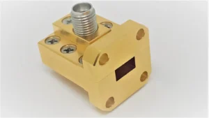
Yes. A coaxial instrument port may connect through a waveguide-to-coax transition to a waveguide assembly. The transition’s band, matching, insertion loss and power limit then belong in the system budget.
Which choice is better for an OEM design?
Choose the assembly that meets the band, loss, power, mechanical and service requirements with documented test conditions. If both meet those limits, compare installed cost, connector access, replacement availability and the work needed to reproduce the measured performance.