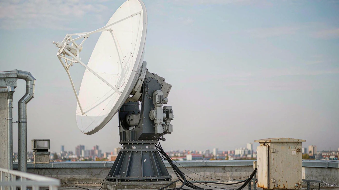
LEO ground stations need tracking antennas because the satellite’s direction changes throughout each pass. A high-gain antenna has a narrow beam, so the station must steer that beam to keep pointing loss within the link budget. Tracking preserves the useful contact window for data reception and commands. It can use a moving dish or an electronically steered beam; a wide-beam, low-rate link may not need directional tracking.
Table of Contents
Why Fixed Dishes Work for GEO
A geostationary satellite orbits above the equator in step with Earth’s rotation. Its orbital period is 23 hours 56 minutes and 4 seconds, at about 35,786 km altitude. It therefore appears nearly stationary from the ground, allowing a fixed dish to serve the link [1].
LEO generally lies below 2,000 km. Representative values are about 7.8 km per second and roughly 90 minutes per orbit, depending on altitude and orbit shape [2]. NASA gives the International Space Station as an example: about 250 miles (about 400 km) high, moving at 17,500 mph (about 7.8 km per second), with an orbit of about 90 minutes [3]. That period means about 24 × 60 / 90 ≈ 16 orbits per day, not 16 visible passes at one station. Local contact opportunities depend on the orbit, station location, obstructions, and minimum usable elevation.
A LEO Pass From the Ground
For an illustrative overhead pass, assume a 550 km slant range at closest approach and a transverse speed relative to the station of 7.5 km per second. The instantaneous line-of-sight rate is approximately v/r = 7.5/550 = 0.0136 radians per second, or 0.78 degrees per second. This local straight-line model neglects Earth rotation and orbital curvature. It is a sizing example, not a predicted rate for every pass.
Each mount axis must follow its own commanded trajectory. A line-of-sight rate is not automatically the required azimuth or elevation motor speed; axis geometry, acceleration, travel limits, and overhead-pass behavior must also be checked.
High Gain Means Narrow Beams
Dolph Microwave’s published LEO/MEO tracking antenna specifications illustrate how aperture and band change the pointing requirement. These are manufacturer-listed configuration values, not independent test results.
| Configuration | Gain | Half-power beamwidth |
|---|---|---|
| 2.4 m X-band | 45 dBi | 0.9 to 1.0 degrees |
| 3.7 m X-band | 47.63 dBi | 0.6 degrees |
| 3.7 m S-band | 35.38 dBi | 2.4 degrees |
The listed 2.4 m X-band version covers 9.3 to 9.7 GHz downlink. The 3.7 m S+X version covers 8.025 to 8.4 GHz and 2.2 to 2.3 GHz downlink, with 2.025 to 2.1 GHz uplink. Published antenna noise temperatures are at most 77 K for the 2.4 m dish, and 85 K in X-band and 130 K in S-band for the 3.7 m dish. These are antenna temperatures, not complete receiver-system noise temperatures. The tables list VSWR at most 1.5:1 and Tx/Rx isolation of 80 dB; confirm applicability to the selected ports and bands, especially for the downlink-only example. A waveguide diplexer can separate transmit and receive bands sharing a common RF port.
The platform lists pointing accuracy better than one-sixth of the half-power beamwidth. On a 0.9-degree beam, one-sixth is 0.15 degrees. Treat this as a configuration-specific target, not a universal rule. The listed program-tracking accuracies are RMS values; they do not establish a maximum instantaneous error or prove compliance under every wind and radome condition.
For a worked estimate, assume a Gaussian main beam and define beamwidth as the full half-power width. Pointing loss is approximately 12 × (angular error / beamwidth)² dB. A fixed 0.09-degree offset on a 0.9-degree beam gives 0.12 dB; a 0.3-degree offset gives 1.33 dB. These are static-offset calculations, not measured losses or predictions from an RMS tracking specification. Other link losses are excluded. Large offsets need the measured antenna pattern, and loss of lock depends on remaining link margin.
A separate aperture check uses theta ≈ 70 × lambda / D, with theta in degrees and lambda and D in meters. At 8.2 GHz, lambda is about 0.0366 m, giving roughly 1.07 degrees for a hypothetical 2.4 m dish. The factor 70 represents an assumed illumination taper. This is not the beamwidth specification of the listed 2.4 m model, whose downlink range is 9.3 to 9.7 GHz.
The table lists X-band WR112 and S-band N-type feed interfaces and 35 dB cross-polarization isolation. Match the feedhorn and feed interface to the selected reflector, band, and polarization. An orthomode transducer separates orthogonal polarization paths. Specify the horn, polarization components, filters, and diplexers as a compatible antenna feeder network; these components manage the RF path but do not steer the beam.
What Tracking Does
Program Tracking
Program tracking predicts where to point from orbital information. Dolph lists two-line element set (TLE) input; the controller also needs the station position, time, and mount calibration. Confirm the supported orbit-propagation method and update interval. Old orbital elements, incorrect coordinates, or a clock offset can move the predicted path away from the spacecraft.
Automatic Tracking
The platform offers monopulse automatic tracking for high frequencies and larger apertures. This uses received-signal pointing-error information to correct the predicted direction. A possible sequence is program-track acquisition followed by signal-based tracking after lock. Specify the signal threshold for that transition and the controller’s fallback behavior if the signal disappears.
Pedestals and Controllers
The mount has to handle big swings and tiny creeps in the same pass. A waveguide rotary joint carries the RF signal across the rotating waveguide sections while the axes move.
- Travel: minus 90 to plus 90 degrees on each X/Y axis.
- Angular velocity: 0.01 to 10 degrees per second.
- Encoder resolution 0.005 degrees or better, servo position resolution 0.01 degrees or better, and backlash below plus or minus 1 arc minute.
- Manufacturer-listed program tracking accuracy: better than 0.09 degrees RMS for the 2.4 m version and 0.07 degrees RMS for the 3.7 m version.
Encoder resolution is not tracking accuracy. Request the test conditions, error definition, wind limits, and radome configuration behind the accuracy figures. The 3.7 m table identifies a 5.9 m radome; do not assume the same performance for a different installation.
Electronic Beam Steering
Tracking does not require a moving reflector. An electronically steered array can change beam direction while its panel stays fixed. NASA’s ground-systems overview includes phased-array systems among direct-to-Earth ground-station options. The essential requirement is to follow the spacecraft’s line of sight, whether steering is mechanical or electronic [4].
Receivers Must Track Doppler
Antenna pointing and frequency tracking are separate tasks. Motion toward or away from the station creates Doppler shift. The receiver or modem must accommodate that shift through its acquisition range, tracking loop, or frequency prediction. A two-way system also needs a coordinated uplink frequency plan; receive-only stations have no uplink to compensate.
For a first-order, one-way calculation, |delta f| ≈ f × |vr| / c. An assumed radial speed of 7 km per second gives about 191 kHz at 8.2 GHz and 51 kHz at 2.2 GHz. The calculation uses vacuum light speed rounded to 299,792 km per second and excludes atmospheric effects and oscillator drift; NIST gives the exact constant as 299,792,458 meters per second [5]. Radial speed varies through the pass and reaches zero at minimum slant range in the ideal geometric model. These frequency offsets do not occur at that instant.
A 550 km straight-up trip takes 550 / 299,792 seconds. That is about 1.83 ms one way. Slant paths run longer, and processing adds its own bit.
From One Satellite to the Next
A conventional single-beam dish follows one spacecraft at a time. Back-to-back contacts require enough time to slew, settle, and reacquire. Two antennas can provide overlap when both target geometries permit it, while geographically separated stations can provide additional contact opportunities. None of these arrangements guarantees uninterrupted coverage.
Count only the part of a pass above the site’s elevation mask and free of blocking obstructions. Define the permitted handover gap and any required overlap in the acceptance plan. Dolph’s 2.4 m S+X TT&C antenna system article provides related application context; it is a different configuration from the 2.4 m X-band example in the table above.
What Happens Without Tracking
In the overhead example, a satellite moving centrally across a fixed 1-degree beam at approximately 0.78 degrees per second crosses the full half-power width in about 1 / 0.78 ≈ 1.3 seconds. This is not the total visibility window or a hard reception cutoff: reception outside that width depends on antenna response and link margin. It shows why a fixed narrow beam cannot retain its peak gain throughout the pass.
A wide-beam antenna may support a low-rate LEO link if the link budget closes. It does not guarantee beacon reception, and a tracked antenna does not guarantee a particular data rate. Required gain, spacecraft transmit power, bandwidth, coding, and allowed outage determine the choice.
Fixed or Tracking Antenna
| Requirement | Fixed pointing may work | Directional tracking is appropriate |
|---|---|---|
| Look direction | Nearly stationary geostationary target | Moving target leaves the useful high-gain beam |
| Link budget | Wide-beam gain is sufficient over the required contact | Narrow-beam gain is needed to meet margin |
| Service window | Short or intermittent reception is acceptable | Pointing must be maintained across the usable pass |
| Implementation | Fixed broad coverage | Mechanical dish steering or electronic beam steering |
A Worked Commissioning Scenario
Consider an illustrative station review using the 0.9-degree beam and 0.78-degree-per-second pass rate above. A one-sixth-beam allowance is 0.15 degrees. If timing offset were the only error, a local estimate gives 0.15 / 0.78 ≈ 0.19 seconds before that allowance is consumed. Real stations must share the budget among time, orbit prediction, alignment, servo error, and structural deflection, so 0.19 seconds is not a clock specification.
If acquisition occurs but the signal fades near closest approach, compare the predicted trajectory, commanded axis positions, encoder positions, and received level on a common time base. A following error points toward motion-control investigation; correct axis following with a signal offset calls for checks of alignment, orbit inputs, and timing. If pointing appears consistent but carrier lock fails, inspect frequency offset and modem acquisition limits separately. These are diagnostic branches, not proof of a single fault.
For acceptance, record the spacecraft or simulator input, orbit-data epoch, station coordinates, time source, band, polarization, elevation mask, weather, radome state, and measured pointing or signal traces. Compare the results with agreed limits across acquisition, overhead motion, and loss of signal. This scenario is a calculation-led checklist, not a report of a field test.
Checklist Before Quotation
- Which spacecraft and orbits must you support, and what are your minimum elevation and pass-cadence requirements?
- What are your transmit and receive bands, polarization, gain, beamwidth, and system noise temperature?
- What pointing loss can your link tolerate: program tracking alone or program plus automatic tracking?
- How fast must your mount slew and settle for overhead passes and back-to-back handovers?
- How does your modem handle Doppler across all your bands?
- What are your site limits: wind, radome need, installation envelope, power, network, and maintenance access?
To size the tracking antenna your station needs, list your orbit, frequency plan, polarization, feed interface, tracking method, and site limits in one request.
Short Answer
A LEO ground station needs directional tracking when the link requires a narrow, high-gain beam throughout a moving pass. Steer the beam to control pointing loss, handle Doppler in the radio system, and schedule reacquisition around the actual contact geometry. Use a wide-beam fixed antenna only when its coverage and link margin meet the mission requirement.
Planning a LEO tracking ground station?
Send your orbit, frequency plan, polarization, and site limits, and our engineers will review the antenna and feed configuration with you.
Request a Technical Review