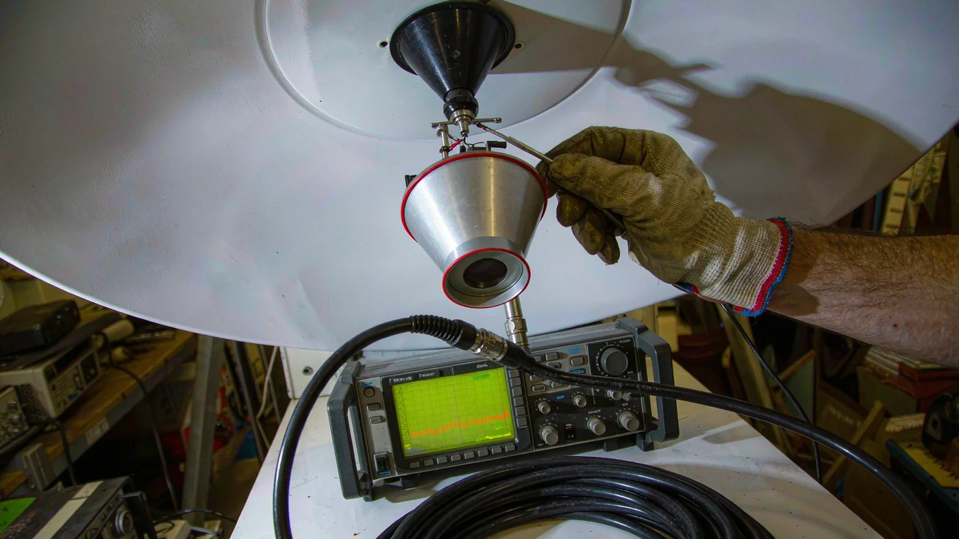
A higher antenna G/T improves satellite reception by increasing the carrier-to-noise ratio. With the same satellite signal, path losses, and receiver noise bandwidth, a 1 dB increase in G/T gives a 1 dB increase in downlink C/N. That improvement can provide more fade margin, reduce errors near the decoding threshold, or support a higher data rate when the modem and service allow it.
G/T combines antenna gain with system noise temperature. It is the receiving system’s figure of merit, not a measure of signal strength alone. Gain and noise temperature must refer to the same reference plane for the ratio to be meaningful. ITU-R S.733 describes G/T determination for fixed-satellite-service earth stations [1].
Table of Contents
What a G/T Change Does to Reception
G/T in dB/K = G in dBi − 10 × log10(Tsys in kelvin).
G is the receive antenna gain at the operating frequency; Tsys includes external antenna noise and receiver-chain noise referred to the same point. A larger dish can increase G. A quieter receiver or lower loss ahead of the low-noise amplifier can reduce Tsys. General radio-noise sources and prediction methods are covered by ITU-R P.372 [2].
Consider a calculated example with gain held at 41.4 dBi. Doubling system noise temperature from 150 K to 300 K reduces G/T by 3.01 dB, even though the dish has not changed.
| Receive system | Gain | System temperature | G/T |
|---|---|---|---|
| Lower-noise system | 41.4 dBi | 150 K | 19.6 dB/K |
| Higher-noise system | 41.4 dBi | 300 K | 16.6 dB/K |
Under otherwise identical conditions, the higher-noise system loses 3.01 dB of downlink C/N. Whether reception then fails depends on the modem’s required C/N and the margin available before that loss.
How Front-End Loss Changes G/T
Use one reference plane throughout the calculation. For an antenna feeding a passive loss followed by a receiver, the antenna-input-referred system temperature is Tsys = Ta + (L − 1)Tp + L × Tr. Here Ta is antenna noise temperature, L is the linear loss factor, Tp is the lossy component’s physical temperature, and Tr is receiver noise temperature at the receiver input. McMaster University’s antenna-noise lecture derives the input-referred loss temperature and the output-to-input temperature transformation [3].
For this worked example, assume Ta = 70 K, made up of 40 K of sky and atmospheric noise plus 30 K of ground pickup; Tp = 290 K; and Tr = 40 K. These are calculation assumptions, not measured equipment specifications.
| Pre-LNA loss | Linear loss L | Loss noise (L − 1)Tp | Referred receiver noise L × Tr | Total Tsys |
|---|---|---|---|---|
| 0.5 dB | 1.1220 | 35.4 K | 44.9 K | 150.3 K |
| 0.3 dB | 1.0715 | 20.7 K | 42.9 K | 133.6 K |
Reducing that loss from 0.5 dB to 0.3 dB improves G/T by 10 × log10(150.3/133.6), or about 0.51 dB, with antenna gain held fixed. Do not add another 0.2 dB of recovered signal gain: at this reference plane, the loss effect is already included in Tsys. If using gain after the loss instead, refer every noise contribution to that downstream plane too.
How G/T Becomes Carrier-to-Noise Ratio
C/N0 in dBHz = EIRP in dBW − propagation and other applicable losses in dB + G/T in dB/K + 228.6.
C/N0 is carrier power divided by noise power density. The constant 228.6 comes from −10 × log10(k), where the Boltzmann constant k is exactly 1.380649 × 10⁻²³ J/K [4].
For a calculated Ku-band GEO downlink, assume EIRP = 46 dBW, distance = 38,000 km, frequency = 12 GHz, and 3 dB of additional losses not already represented in station G/T. The free-space loss is about 205.63 dB, using the free-space attenuation relation covered by ITU-R P.525 [5].
| Station G/T | Calculated C/N0 | C/N in 36 MHz | C/N in 2 MHz |
|---|---|---|---|
| 14 dB/K | 80.0 dBHz | 4.4 dB | 17.0 dB |
| 17 dB/K | 83.0 dBHz | 7.4 dB | 20.0 dB |
| 20 dB/K | 86.0 dBHz | 10.4 dB | 23.0 dB |
Convert with C/N = C/N0 − 10 × log10(B), using noise bandwidth B in hertz. The subtraction is 75.56 dB for 36 MHz and 63.01 dB for 2 MHz. The table holds carrier power constant; it does not imply that narrowing a service’s bandwidth preserves its data rate or allocated satellite power.
A 3 dB G/T improvement gives 3 dB more thermal-noise margin in this downlink calculation. Rain can both attenuate the carrier and increase antenna noise temperature, so clear-sky G/T alone does not establish wet-weather availability. ITU-R P.618 provides Earth-space propagation prediction methods [6].
These values describe the downlink thermal-noise contribution. For a complete communications link, also account for uplink noise, interference, and implementation losses. NASA’s ground-systems overview discusses link budgets and the ground segment’s role in communications design [7].
When a Larger Dish Improves Reception
For a circular aperture, linear gain is G = η × (πD/λ)2, where η is aperture efficiency, D is diameter, and λ is wavelength. Convert linear gain to dBi with 10 × log10(G). NASA reflector analysis describes this gain–aperture relationship [8].
| Dish diameter | Frequency | Wavelength | Calculated gain at η = 0.6 |
|---|---|---|---|
| 0.9 m | 12 GHz | 25.0 mm | 38.9 dBi |
| 1.2 m | 12 GHz | 25.0 mm | 41.4 dBi |
| 2.4 m | 12 GHz | 25.0 mm | 47.4 dBi |
| 1.2 m | 4 GHz | 74.9 mm | 31.8 dBi |
| 1.2 m | 20 GHz | 15.0 mm | 45.8 dBi |
The calculations use c = 299,792,458 m/s and λ = c/f. Doubling diameter from 1.2 m to 2.4 m adds 6.02 dB of gain at the same frequency and efficiency. That becomes 6.02 dB of G/T improvement only if system temperature is unchanged. If temperature also doubles, the net improvement is 3.01 dB; if it quadruples, the gain advantage is canceled.
The higher-frequency rows show antenna gain, not a promise of better reception. For the same physical aperture, distance, efficiency, and EIRP, the frequency-related gain increase is offset by the increase in free-space path loss. Atmospheric loss, system temperature, pointing, and the satellite’s actual EIRP must then be evaluated separately.
What Extra G/T Cannot Fix
- Incompatible receive hardware. The feed, LNB RF range, local-oscillator plan, and modem must match the service. Check the satellite LNB receive-range and LO selection guidance rather than relying on a band-family label alone.
- Interference from the same direction. A narrower beam can reject an off-axis interferer, including one using the same frequency. It cannot spatially separate wanted and unwanted signals arriving from the same direction. G/T describes thermal-noise performance, not carrier-to-interference ratio.
- An inadequate uplink. A receive G/T improvement does not itself increase transmit EIRP. In shared-feed systems, check the waveguide diplexer transmit and receive passbands separately.
- Tracking or synchronization failures. More receive sensitivity does not replace the tracking, Doppler compensation, or handover capabilities required by the particular non-geostationary service.
How to Choose a Reception Upgrade
Compare Changes Under the Same Conditions
For an upgrade assessment, record frequency, elevation, weather, polarization, reference plane, antenna gain, system temperature, and receiver noise bandwidth. Compare a baseline and a proposed configuration without changing the satellite carrier or measurement settings. A receiver’s signal-strength display alone cannot establish G/T.
Use the front-end calculation above as a decision example. Reducing loss from 0.5 dB to 0.3 dB yields about 0.51 dB of G/T. Doubling dish diameter yields 6.02 dB if efficiency and temperature remain fixed. These are different-sized gains: a connector or filter change may recover a small deficit, but it cannot be assumed to replace a much larger aperture upgrade.
Check the Feed and Receiver Together
Inspect the feedhorn illumination and reflector compatibility, then total the loss of every component ahead of the LNA. Use waveguide filter passband and insertion-loss specifications at the actual receive frequency, not just a headline minimum. A good VSWR alone does not establish aperture efficiency, spillover noise, or system G/T.
Confirm feed position, focus, pointing, and polarization before assigning a low C/N reading to the receiver. For dual-polarized systems, verify the orthomode transducer polarization-port arrangement through the complete feed path.
Translate the Gain Into Link Margin
There is no universally good G/T value. The requirement depends on the satellite EIRP, propagation losses, noise bandwidth, modem threshold, and availability target. For a worked decision using the 17 dB/K row, assume a modem requires 6.0 dB C/N in 36 MHz. The calculated 7.4 dB leaves about 1.4 dB of margin. Moving to 20 dB/K raises C/N to 10.4 dB and margin to about 4.4 dB. The 6.0 dB threshold is an assumption; substitute the service’s specified value.
Do not subtract feed loss twice if it is already included in station G/T. Evaluate interference separately and combine noise contributions in linear units where required, rather than treating every impairment as a simple attenuation. Check the resulting margin against the intended weather and elevation conditions.
All numerical examples here are reproducible calculations, not installation measurements. For a site-specific recommendation, measured or validated station G/T and the service’s link budget are needed. The useful question is not simply which antenna has more gain, but which change delivers enough G/T to meet the reception requirement.
Planning a receive upgrade keyed to G/T?
Share your receive frequency, dish size, front-end losses, and target link margin to discuss feed and waveguide component requirements.
Discuss Your Receive Requirements