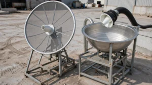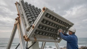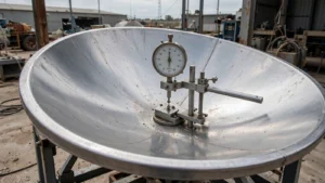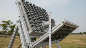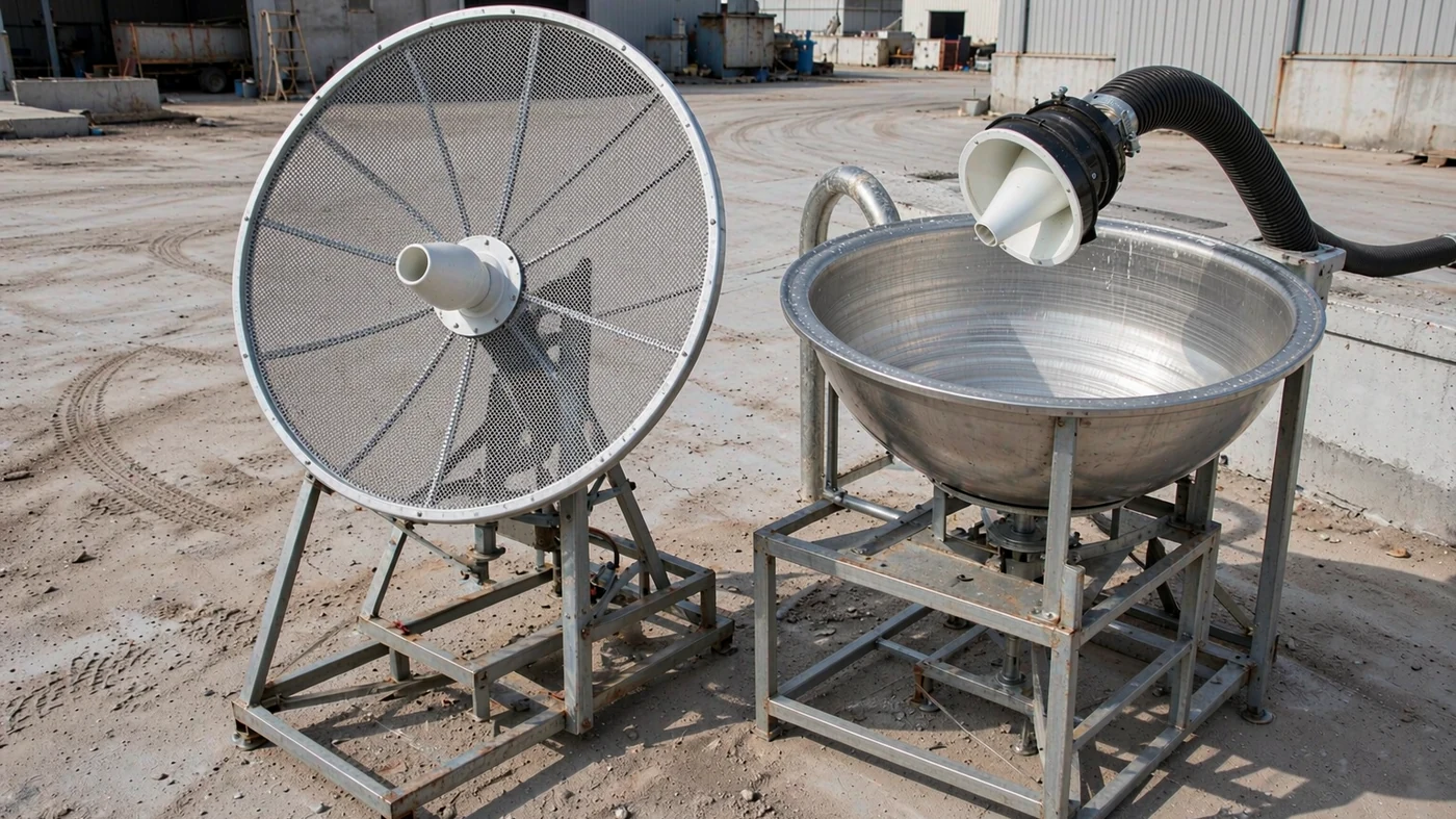
Mesh satellite dishes use an open conductive screen; solid dishes use a continuous reflecting surface. Mesh can reduce reflector weight and wind loading on large antennas, while solid reflectors are usually the simpler choice when short wavelengths demand a precise surface. Neither type has an automatic gain advantage: compare diameter, efficiency, surface accuracy, and the operating band. Surface errors become more costly as wavelength decreases, regardless of reflector construction [1].
Table of Contents
Mesh vs Solid at a Glance
| Factor | Mesh dish | Solid dish |
|---|---|---|
| Reflecting surface | Conductive screen supported by a frame | Continuous conductive surface, including joined solid panels |
| Weight | Can reduce reflector mass for a large aperture | Depends on material, thickness, and support structure |
| Wind | Openings can reduce loading; actual benefit depends on the design | No airflow through the reflecting skin; use the complete antenna’s load ratings |
| Frequency fit | Mesh geometry and surface accuracy must suit the shortest operating wavelength | Often preferred for Ku/Ka terminals, but still needs verified surface accuracy |
| Inspection focus | Tears, slack mesh, panel alignment, and fasteners | Dents, warped panels, joints, and feed alignment |
A published deployable-antenna study used lightweight silver-coated Teflon mesh to increase aperture diameter while limiting mass. It also showed why a reflective screen alone is not enough: deformation of the supporting structure degraded antenna performance [2].
Which Frequency Bands Suit Each Type?
As a practical starting point, consider mesh for a large C-band installation where weight and wind exposure matter, and solid for a conventional Ku- or Ka-band terminal. These are selection preferences, not physical cutoffs. Engineered mesh can operate at shorter wavelengths when its geometry, conductivity, tension, and supporting frame are suitable.
ESA lists C-band as 4–8 GHz, Ku-band as 12–18 GHz, and Ka-band as 26–40 GHz. These broad letter-band ranges are not the exact transmit or receive allocations of every satellite service. Obtain the actual operating frequencies before choosing a reflector or feed [3].
Do Mesh Holes Lose Signal?
They can, but visible openings do not mean the same fraction of radio energy passes through. Reflection depends on the mesh structure relative to wavelength. In the published study, a model of a particular silver-coated Teflon mesh with 20 openings per inch had reflectivity above 97% over 2–18 GHz. That result applies to that mesh and analysis, not to every garden screen or commercial mesh dish [2].
For an illustrative uniform mesh with 20 openings per inch, the nominal repeat pitch is 25.4 / 20 = 1.27 mm. Pitch is not clear-hole width: the strands occupy part of each repeat. Using wavelength = c / frequency, with c = 299,792,458 m/s, gives the following comparison [4].
| Frequency | Free-space wavelength | 1.27 mm pitch relative to wavelength |
|---|---|---|
| 4 GHz | 74.95 mm | About 1/59 |
| 12 GHz | 24.98 mm | About 1/20 |
| 18 GHz | 16.66 mm | About 1/13 |
| 30 GHz | 9.99 mm | About 1/8 |
These ratios show how the same mesh becomes electrically coarser at higher frequencies. They do not establish a universal leakage threshold or predict gain. The cited mesh analysis stops at 18 GHz; its reflectivity result should not be extended to 30 GHz without further evidence.
Surface Accuracy Matters More at High Frequencies
Both constructions must hold the intended paraboloid. A solid skin does not guarantee accuracy, and a fine mesh cannot compensate for a distorted frame. For random surface errors described by the Ruze model, the surface-efficiency factor is exp[-(4 × pi × sigma / wavelength)2], where sigma is RMS surface error. RMS describes the error across the surface, not the depth of one isolated dent [1].
NRAO notes that surface efficiency declines rapidly as RMS error exceeds about wavelength/16. This is a rough reference, not a low-loss acceptance limit. Substituting wavelength/16 into the equation gives approximately 54% surface efficiency, or 2.68 dB loss. A link with less loss allowance needs tighter accuracy [1].
| Frequency | Wavelength/16 reference | Calculated loss with 1.0 mm RMS error |
|---|---|---|
| 4 GHz | 4.68 mm | 0.12 dB |
| 12 GHz | 1.56 mm | 1.10 dB |
| 18 GHz | 1.04 mm | 2.47 dB |
| 30 GHz | 0.62 mm | 6.87 dB |
The error is assumed for illustration. These figures describe the modeled surface-error loss alone, not total antenna efficiency. Feed displacement, panel steps, and localized damage can require a more specific analysis.
A Worked Selection Scenario
Suppose you are comparing reflectors with a documented 1.0 mm RMS surface error for a 12 GHz receive link and a 30 GHz link. The table predicts about 1.10 dB surface loss at 12 GHz but 6.87 dB at 30 GHz. If your assumed surface-loss allowance is only 1 dB, that accuracy misses the target at both frequencies, especially at 30 GHz. Choosing a solid reflector helps only if its verified accuracy meets the requirement; changing the material label alone does not close the link.
Does Mesh or Solid Give More Gain?
At equal diameter, frequency, and aperture efficiency, the calculated gain is the same. The relation is G = efficiency × (pi × diameter / wavelength)2, with gain in dBi equal to 10 × log10(G). Construction changes the result through efficiency and the shape the antenna maintains in service [5].
| Diameter | Gain at 4 GHz | Gain at 12 GHz | Gain at 30 GHz |
|---|---|---|---|
| 1.2 m | 31.8 dBi | 41.4 dBi | 49.3 dBi |
| 2.4 m | 37.8 dBi | 47.4 dBi | 55.3 dBi |
These are calculated on-axis values assuming 60% total aperture efficiency at every frequency, not product specifications. Doubling diameter adds approximately 6.02 dB under that assumption. Do not apply the surface-loss table again if the chosen total efficiency already includes that loss.
Wind, Weight, and Installation
Mesh openings can let some air pass through, but they do not make a dish windproof. Porosity, orientation, frame geometry, and mounting all affect the load. A lightweight reflector also does not automatically make the entire antenna assembly lighter. Compare documented assembly mass and wind loads rather than assuming a fixed percentage saving.
Wind can deform a reflector and reduce performance before structural failure occurs [1]. Ask separately about operating-wind limits and survival ratings, including their stated conditions. A survival rating is not a promise of usable pointing or gain at that wind speed. Severe winds are a real damage hazard; NWS guidance provides weather-safety context, not an antenna structural rating [6].
Inspection and Upkeep
For solid reflectors, inspect dents, warped panels, joints, and the feed support. For mesh, inspect tears, slack areas, panel alignment, and loose fasteners. Surface distortion affects phase and focusing; mesh-frame deformation also affects the radiation pattern [1] [2].
After damage or a storm, photograph visible changes and compare them with installation records. Visual inspection can identify a problem, but it cannot certify submillimeter RMS accuracy. Request the manufacturer’s prescribed checks and, where needed, a surface survey or RF performance test. Feed alignment and reflector accuracy are separate checks; re-pointing alone does not repair a distorted surface.
Which Dish Should You Choose?
Start with the service frequencies, required gain, and polarization. The feed system, including any orthomode transducer, must suit the required polarization paths.
- For a large C-band installation, shortlist mesh where weight or wind loading matters, then verify the complete antenna’s gain and structural ratings.
- For a conventional Ku/Ka terminal, start with a solid reflector designed for the service. Consider mesh only with relevant performance evidence.
- For portable installations, compare packed size, assembly mass, and deployment needs. A 1.2 m quick-deploy flyaway antenna is a size-and-format example, not evidence that all small reflectors perform alike.
- Check the feedhorn against the reflector geometry, focal ratio, and band. Its phase center must be positioned appropriately for the focus [1].
When comparing SATCOM antennas, request gain across the actual band, documented RMS accuracy, mesh geometry where relevant, assembly mass, and operating/survival wind conditions. Include the mount and foundation in the installed-cost comparison. Mesh is attractive when an open, lightweight reflector meets those requirements; solid is attractive when a continuous surface delivers the required precision. Choose the verified antenna, not the surface label.
Not sure which reflector fits your band and site?
Send your operating frequencies, required gain, aperture size, and site constraints.
Discuss Your RequirementsSources
- NRAO, Essential Radio Astronomy, Chapter 3: reflector focusing, surface error, and the Ruze equation. Read the chapter.
- Design of a Deployable Broadband Mesh Reflector Antenna for a SIGINT Satellite System Considering Surface Shape Deformation, Sensors, via PMC: specific mesh modeling and prototype results. Read the study.
- ESA: broad satellite frequency-band designations. Satellite frequency bands.
- NIST: exact speed of light used in the wavelength calculations. Speed of light in vacuum.
- University of Hawaii OER: antenna gain and link-budget relationships. Link-budget chapter.
- U.S. National Weather Service: general wind hazards and safety. Wind safety.