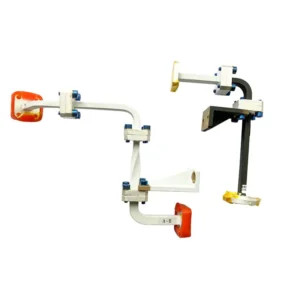
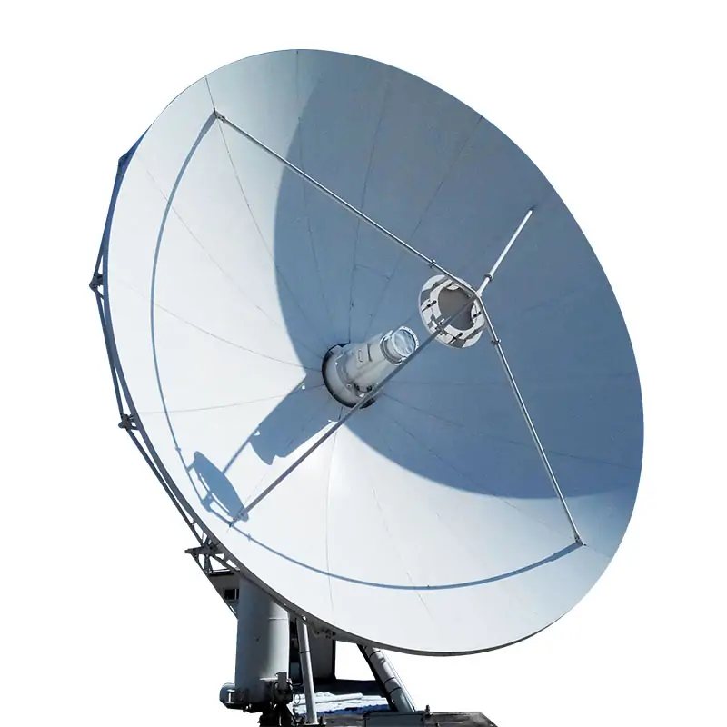
Choosing 915 MHz instead of 2.45 GHz changes the source, waveguide dimensions, circulator, tuner, and cavity feed design. Power and cooling ratings still depend on the operating load. A typical 915 MHz line uses WR975 waveguide; 2.45 GHz lines commonly use WR340 or WR430. Components must match the source’s operating frequency range as well as its continuous output and worst-case reflected power.
For a frequency conversion, expect to replace most frequency-specific RF components. The power supply, cooling equipment, and conveyor may remain usable after their electrical, thermal, and process limits have been checked.
What Changes With Frequency?
| Component | What changes | What determines the final rating |
|---|---|---|
| Microwave source | Operating frequency, output interface, and compatible power supply. | Required RF output, duty cycle, control range, and permitted reflection. |
| Waveguide and bends | Cross-section, cutoff frequency, flange size, and installation space. | Continuous and peak power, loss, mismatch, and temperature. |
| Circulator and absorbing load | Operating band, matching, and waveguide interfaces. | Forward power, reverse power, fault duration, and cooling. |
| Tuner and coupler | Electrical dimensions, matching range, and frequency response. | Load variation, power capacity, tuning speed, and measurement accuracy. |
| Window and cavity feeds | Window matching, feed geometry, and cavity field distribution. | Product properties, temperature, pressure, and heating uniformity. |
Waveguide Size and Interfaces
| Parameter | 915 MHz | 2.45 GHz |
|---|---|---|
| Free-space wavelength | About 32.8 cm | About 12.2 cm |
| Common waveguides | WR975 | WR340, WR430 |
| Internal dimensions | WR975: 247.65 × 123.83 mm | WR340: 86.36 × 43.18 mm WR430: 109.22 × 54.61 mm |
| Dominant-mode cutoff frequency | WR975: about 0.605 GHz | WR340: about 1.736 GHz WR430: about 1.372 GHz |
WR975 is about 2.87 times wider internally than WR340. Installation drawings must also allow for walls, waveguide flanges, supports, and tool access. The WR designation identifies the waveguide size; it does not guarantee that two flange patterns or seals will fit.
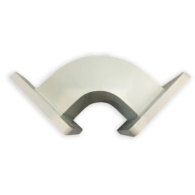
Specify bend angle, E-plane or H-plane orientation, and flange-to-flange dimensions.
915 MHz is below WR340’s dominant-mode cutoff, so ordinary hollow WR340 cannot serve as a conventional 915 MHz transmission line. A mechanical adapter cannot correct this. The cutoff values above are calculated for air-filled rectangular waveguide; loaded and ridged structures require separate analysis.[1]
Source Frequency and Component Bandwidth
A component labeled “915 MHz” or “2450 MHz” still needs a specified operating band. A magnetron’s frequency can shift with temperature, operating power, and load conditions. A frequency-adjustable solid-state source may also operate across a range rather than at one fixed point.
Use the source manufacturer’s minimum and maximum operating frequencies when checking the circulator’s isolation, tuner performance, coupler calibration, and window matching. A component that meets its specification only at the center frequency may not meet it across the source’s full range.
Component bandwidth and permitted emission bandwidth are different specifications. A broad component rating does not authorize the system to operate across that entire band.
Product Thickness and Cavity Feeds
In food materials, 915 MHz often provides greater penetration than 2.45 GHz, but the difference depends on the material’s dielectric properties at each frequency. The wavelength ratio of 2.68 is not a penetration-depth multiplier. Composition, temperature, and product thickness also affect heating performance.[2]
Test feed position and coupling with the actual product. If a drying process moves from 30% to 10% moisture on a wet basis, include both endpoints and any intermediate condition where reflection rises or heating becomes uneven. Record internal and surface temperatures rather than relying on an average outlet temperature.
Source and Power Distribution
Both frequencies can use magnetron or solid-state sources. Compare RF output separately from electrical input. If the process needs 20 kW for heating and 2 kW for holding, specify whether the lower setting must be continuous or may be produced by on/off cycling.
| Example architecture | Component requirements |
|---|---|
| One 20 kW source | The transmission path must handle 20 kW continuously under the specified mismatch conditions. |
| Four 5 kW sources with separate feeds | Each forward path carries its own source output. Reverse-power protection must account for energy coupled from the other feeds through a shared cavity. |
| Four 5 kW sources with a combiner | Check source compatibility, combiner loss and isolation, and combined-path power capacity. Coherent combining may require phase control; independent magnetrons cannot simply be assumed suitable. |
If one of four 5 kW sources stops, nominal available power falls to 15 kW. The field distribution also changes, so running at 75% throughput still requires product validation.
Reflected Power and Protection
A microwave circulator must route reflected power to a suitably rated load across the operating band. Its forward-power rating does not establish the load’s reverse-power capacity.
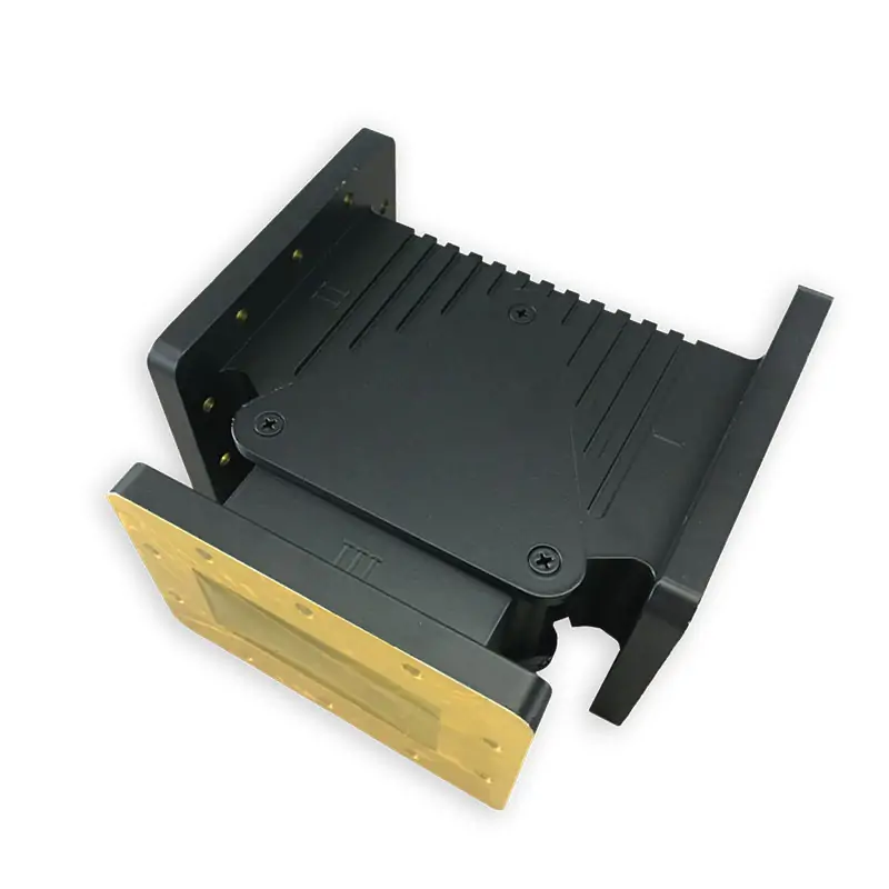
Check isolation and insertion loss across the specified frequency range.
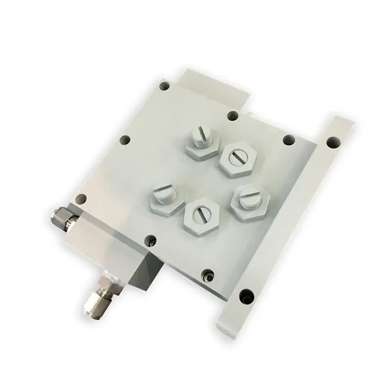
Check absorbed power, permitted duration, and cooling requirements.
The reflected-power fraction is calculated as [(VSWR − 1) ÷ (VSWR + 1)]². At 20 kW forward power:
| VSWR | Reflected fraction | Reflected power |
|---|---|---|
| 1.2:1 | About 0.83% | About 165 W |
| 1.5:1 | 4.0% | 800 W |
| 2.0:1 | About 11.1% | About 2.22 kW |
| 3.0:1 | 25.0% | 5.00 kW |
These values use forward and reflected power at the same reference plane, assuming a single propagating mode. A design that tolerates continuous full reflection at 20 kW needs a load and cooling circuit rated for that duty. A shutdown-based design needs a verified detection-to-power-off time.
At a constant 20 kW reflection, 100 ms corresponds to 2 kJ; one second corresponds to 20 kJ. Energy alone does not qualify the hardware. The supplier must also confirm its limits for electric field, reflection phase, and mismatch duration.
Tuners and Measurement
Manual three-stub tuners suit loads that remain stable after setup. Processes with substantial load changes may need automatic matching. The tuner must cover the expected impedance range, not just the nominal frequency and power.
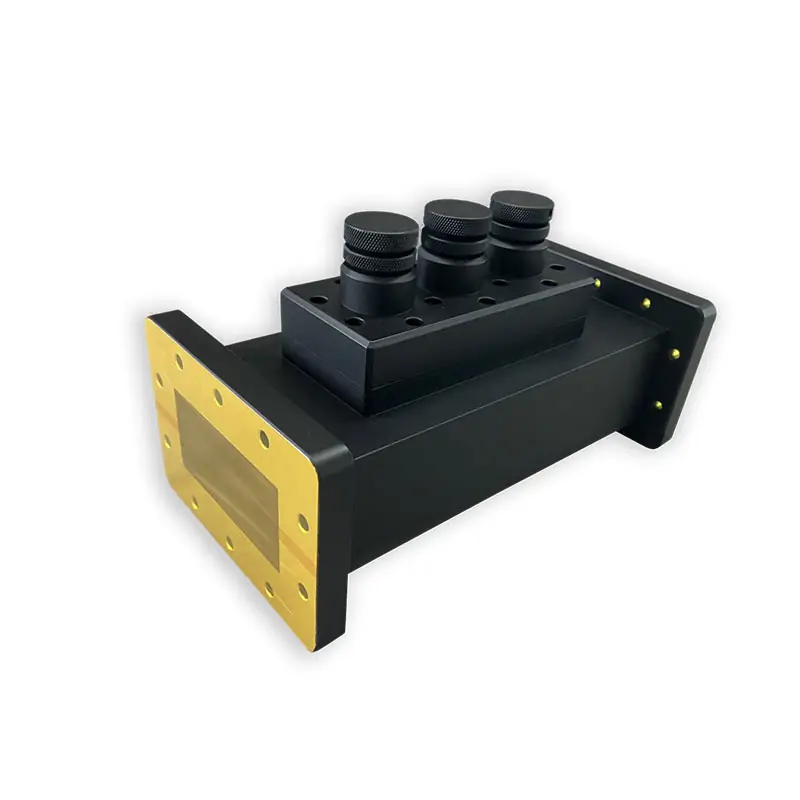
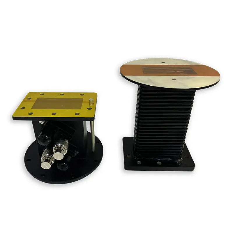
For automatic tuning, request a measured recovery time after an agreed load change. Reducing VSWR from 2.0:1 to 1.2:1 at 20 kW would reduce reflection from about 2.22 kW to 165 W. The report should identify the test load, frequency, and measurement uncertainty.
The coupler and detector need sufficient directionality, measurement range, and response speed. Recalibration cannot extend their hardware frequency range. Arc and high-reflection protection must operate independently of tuning.
Losses and Cooling
At 20 kW input, 0.1 dB insertion loss means about 455 W does not reach the output; at 0.2 dB, the difference is about 900 W. Some may be reflected. Only the absorbed portion becomes heat within the component.
For water near room temperature, the approximate heat-balance calculation is:
Flow (L/min) ≈ 14.3 × heat load (kW) ÷ water temperature rise (°C).
| Heat to remove | Calculated flow |
|---|---|
| 5 kW | About 7.2 L/min |
| 10 kW | About 14.3 L/min |
| 20 kW | About 28.7 L/min |
These values are calculations, not product ratings. The minimum flow for a water load also depends on local heat transfer and the manufacturer’s limits. Select the pump at the combined pressure drop of the load, piping, valves, and heat exchanger.
Cooling requirements follow the actual heat load rather than frequency alone. An existing cooling system can be reused only if it meets the new branch-flow, inlet-temperature, pressure, and water-quality requirements.
Windows and Equipment Reuse
A waveguide pressure window requires both RF and mechanical ratings. Specify material grade, opening, thickness, frequency, power, temperature, and pressure differential. A “0.1 MPa” rating must state whether it is gauge, absolute, or differential pressure, plus the loading direction.
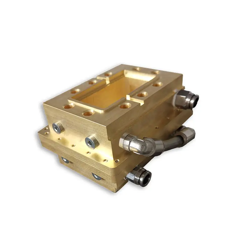
Include dust, condensation, cleaning chemicals, and thermal cycling in the specification.
For other reusable equipment, check the power supply’s voltage, current, regulation, and control interfaces; the frame’s clearance and support loads; and the conveyor’s speed and product-bed limits. Reusing a cavity requires new feed-coupling, heating-uniformity, leakage, and interlock tests.
Acceptance Data to Request
A small-signal RF result does not establish a component’s continuous-power or fault rating. Request records that identify the test conditions:
- RF performance: frequency range, insertion loss, return loss or VSWR, and isolation where applicable.
- Power and temperature: applied continuous power, test duration, cooling conditions, and temperatures after thermal stabilization.
- Reflection protection: applied mismatch, reverse power, fault duration, and measured shutdown delay.
- Process performance: product formulation, loading, temperature distribution, final moisture or other quality endpoint, and accepted throughput.
Frequency Rules and Safety Standards
The ITU’s ISM designation for 902–928 MHz applies to Region 2; the 2400–2500 MHz designation has no equivalent regional restriction. National rules still determine the permitted installation and operating conditions.[3]
IEC 60519-6:2022 covers industrial high-frequency dielectric and microwave heating equipment, including separately supplied generators, alongside the applicable general requirements.[4]