
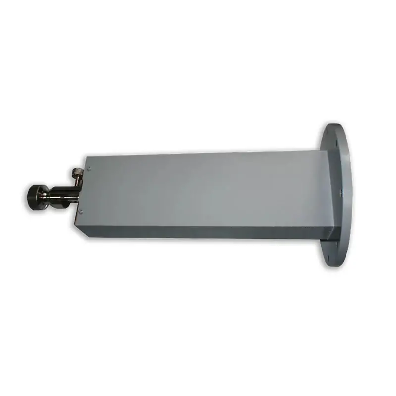
Waveguide Sliding Short
A Waveguide Sliding Short is a precision device used in microwave systems to adjust the phase or impedance at a specific point within a waveguide. It consists of a movable short-circuit that slides along the waveguide, allowing for fine-tuning of the waveguide’s electrical length. This tool is indispensable in research, calibration, and testing applications, offering high accuracy and versatility in adjusting microwave signals.
Tune the reflection position without changing the waveguide section
The movable short-circuit position lets you adjust electrical length for phase or impedance work in calibration, testing and research setups. Standard and custom configurations are reviewed around your waveguide size, flange and mechanical requirements.
What can be specified
Use these published options as the starting point. Exact model dimensions and adjustment details are confirmed for the selected interface.
Send Your RequirementBroad Waveguide Compatibility
Waveguide Size Range: From the largest WR2300 to the smallest WR10, ensuring versatility across various microwave systems.
Precision Adjustment
Type: Adjustable and movable, allowing for precise control over the waveguide’s electrical length for optimal system performance.
High-Quality Construction
Material Options: Available in aluminum (Al) or copper (Cu), chosen for their excellent electrical properties and durability.
Versatile Flange Options
Flange Types: Including cover, grooved, and choke, to accommodate different system requirements and ensure a secure fit.
Low Loss and High VSWR
Performance: Engineered for low loss and high Voltage Standing Wave Ratio (VSWR), maximizing signal integrity and system efficiency.
Published product-page data
Keep the selected WR size and flange interface in the RFQ so the model can be checked against the mating waveguide.
| Specification | Detail |
|---|---|
| Waveguide Size | WR2300 to WR10 |
| Type | Adjustable, movable |
| Material | Aluminum (Al), Copper (Cu) |
| Flange Type | Cover, Grooved, Choke |
| Performance | Low loss, High VSWR |
Have a WR size or mating flange drawing?
Send it with the operating frequency, material preference and quantity. We can review the interface before quotation.
Where adjustable shorting is used
Calibration and Testing
Used where the reflection position needs to be adjusted during microwave component or system measurement.
Research Laboratories
Supports experimental setups that require controlled changes to waveguide electrical length.
Telecommunications
Used in development and maintenance setups that need controlled waveguide tuning.
Radar Systems
Applied in waveguide test paths where phase or impedance adjustment is required.
Satellite Communications
Supports testing and adjustment work around waveguide-based satellite communication hardware.
Sliding or fixed?
Use a sliding short when you need to move the short-circuit position. For a fixed reflection point, review the shorting plate or offset-short options.
Need adjustable phase / impedance work
Stay with the Waveguide Sliding Short.
Need a fixed high-reflection termination point
Compare Waveguide Shorts / Shorting Plates and the offset-short reference.
Need an adjustable matched load instead
Review the Waveguide Sliding Termination.
Send the data that defines the fit
A drawing is useful when the unit must replace an existing part or fit a restricted test fixture.
Send Specs or DrawingWaveguide size and operating frequency
Provide the WR or IEC designation and the frequency range used in your setup.
Flange interface
State the cover, grooved or choke interface, or send the mating flange code/drawing.
Material
Select aluminum or copper, or ask sales engineering to review the required configuration.
Adjustment and mechanical limits
Share the required adjustment function, available installation space and any critical dimensions.
Quantity and supporting files
Include quantity plus any PDF, STEP, sketch, existing part number or marked-up system drawing available.
Built and reviewed by a microwave component manufacturer
Dolph Microwave was founded in 2001 in Xi’an. Published capabilities include CNC machining, turning, waveguide forming and bending, plating, soldering and brazing, and RF vector/scalar measurement support up to 100 GHz.
Company founded
Microwave components and antenna feed systems.
Published RF measurement capability
Vector and scalar measurement support is listed up to 100 GHz.
Published product warranty
Material and workmanship defects are covered for one year from the date of delivery under Dolph Microwave’s published warranty terms.
Original technical PDFs
Use the product and flange documents when checking the waveguide family and mating interface.
Check flange families before fixing the mating interface.
A practical reference for waveguide measurement setup and calibration checks.
Useful when EIA / IEC naming and gasket fit need to be checked together.
Review the wider waveguide range, manufacturing support and order information.
Build the surrounding test setup
Send your WR size, flange and adjustment requirement
We can review a standard requirement, replacement part, modified interface or custom mechanical configuration. Dolph Microwave publishes a one-year warranty covering defects in material and workmanship from the date of delivery.







